|
|
|
|
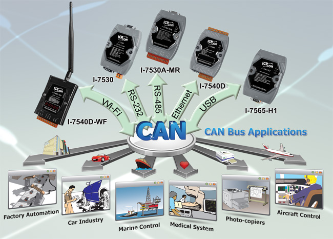
ICP DAS CAN converters are used to establish a physical coupling of two or more communication interface, and are infrastructure components with which complex network structures can be implemented. They can be used to implement the data conversion between CAN and COM, USB or Ethernet interface. By selecting the necessary CAN converters, users can control and integrate the data exchange and transmission between multi-interfaces easily.
|
|
|
|
| CAN Bus Fiber Converter Selection Guide |
|
|
|
| Model Name |
I-2533CS
|
I-2533CS-60 |
I-2533CS-A
I-2533CS-B
*note1 |
I-2533 |
I-2532 |
| Pictures |
 |
|
 |
 |
 |
| CAN Interface |
| Module Type |
 |
|
|
|
 |
| Baud Rate (bps) |
10 k ~ 1 M and user-defined |
10 k ~ 1 M and user-defined |
10 k ~ 1 M and user-defined |
10 k ~ 1 M and user-defined |
10 k ~ 500 k |
| CAN Filter |
Yes |
Yes |
Yes |
Yes |
No |
| 120Ω Terminal Resistor |
Built-in |
Built-in |
Built-in |
Built-in |
Built-in |
| Isolation |
3000 VDC for DC-to-DC, 2500 Vrms for photo-couple |
| Specification |
ISO 11898-2, CAN 2.0A and CAN 2.0B |
| Propagation Delay |
190μs *note2 |
190μs *note2 |
190μs *note2 |
250μs *note2 |
< 120 ns |
| Fiber Interface |
| Type |
SC Duplex type ;
Single mode ;
100Base-FX; |
SC type ;
Single mode ;
100Base-FX; |
ST (Multi-mode) |
ST (Multi-mode) |
| Wave Length (nm) |
1310 |
TX: 1310, RX: 1550 for I-2533CS-A
TX: 1550, RX: 1310 for I-2533CS-B |
850 |
850 |
| Fiber Cable (μm) |
8.3/125, 8.7/125, 9/125 or 10/125 |
8.3/125, 8.7/125, 9/125 or 10/125 |
8.3/125, 8.7/125, 9/125 or 10/125 |
50 / 125, 62.5 / 125, 100 / 140 |
50 / 125, 62.5 / 125, 100 / 140 |
| Max. Fiber Distance (km) |
30 km |
60 km |
15 km |
2 km |
1.4 km |
| Misc. |
| Topology |
One-to-One
One-to-Many |
One-to-One
One-to-Many |
One-to-One
One-to-Many |
One-to-One |
One-to-One |
| Work with Fiber Switch |
Yes |
Yes |
Yes |
No |
No |
| Extend CAN bus Distance |
Yes |
Yes |
Yes |
Yes |
No |
| Repeat CAN bus signal |
Yes |
Yes |
Yes |
Yes |
No |
| Integrate two different networks |
Yes |
Yes |
Yes |
Yes |
No |
*note1:
The I-2533CS-A and I-2533CS-B are a couple and must be used in pairs in CAN Bus applications.
*note2:
The propagation delay depends on the CAN Bus baud rate and the CAN message format. This value has been tested using a CAN baud rate of 1 Mbps, the CAN ID 0x12345678 and 8 bytes of data with a value of 0xFF. |
|
|
|
| CAN Bus Repeater Selection Guide |
|
|
|
| Module Name |
I-7531 |
I-7532 |
I-2534 |
I-5534-M |
| Pictures |
 |
 |
 |
 |
| CAN Interface |
| Module Type |
 |
|
|
|
| Connector |
Screwed terminal block |
Screwed terminal block |
Screwed terminal block |
9-pin male D-Sub |
| Transceiver |
None |
NXP 82C250 |
NXP TJA1042 |
NXP TJA1042 |
| Channel number |
2 |
2 |
4 |
4 |
| Baud Rate (bps) |
5 k ~ 800 k |
5k ~ 1M bps and user-defined |
5k ~ 1M bps and user-defined |
5k ~ 1M bps and user-defined |
| CAN Filter |
No |
Yes |
Yes |
Yes |
| Isolation |
3000 VDC for DC-to-DC,
2500 Vrms for photo-couple |
| 120Ω Terminal Resistor |
Built-in |
Built-in |
Built-in |
Built-in |
| Propagation Delay |
200 ns |
134 us ~ 30 ms
*note1 |
240 us ~ 1360 us
*note1 |
240 us ~ 1360 us
*note1 |
| Misc. |
| Extend CAN bus Distance |
No |
Yes |
Yes |
Yes |
| Repeat CAN bus signal |
Yes |
Yes |
Yes |
Yes |
| Integrate two CAN networks
at
different baud rate |
No |
Yes |
Yes |
Yes |
*note1:
The propagation delay depends on the CAN Bus baud rate and the CAN message format.
The minimum delay is [ 11-bit ID and 8-byte data @ 1M bps ]
The maximum delay is [ 29-bit ID and 8-byte data @ 5k bps ] |
|
|
|
| CAN Bus Converter Selection Guide |
|
|
|
CAN to COM Converter series products:
| Module Name |
I-7530 |
I-7530T |
tM-7530 |
tM-7530A |
I-7530A |
I-7530A-MR |
I-7530-FT |
| Pictures |
 |
|
 |
 |
 |
 |
 |
| CAN Interface |
| CAN Specification |
ISO-11898-2 |
ISO-11898-2 |
ISO-11898-2 |
ISO-11898-2 |
ISO-11898-2 |
ISO-11898-3 |
| CAN Transceiver |
NXP 82C250 |
NXP TJA1042 |
NXP TJA1042 |
NXP 82C250 |
NXP 82C250 |
AMIS 41682 |
| Baud Rate (bps) |
10k ~ 1M bps |
10k ~ 1M bps |
10k ~ 1M bps and user-defined |
10k ~ 1M bps |
10k ~ 1M bps and
user-defined |
10 k ~ 125 k |
| CAN Filter |
Yes |
Yes |
Yes |
Yes |
Yes |
Yes |
| CAN Isolation |
3000 VDC for DC-to-DC, 2500Vrms ~ 3750Vrms for photo-couple |
None |
| Terminal Resistor |
Built-in 120Ω |
Built-in 120Ω |
None |
Yes |
Built-in 120Ω |
Built-in 120Ω |
Built-in 1kΩ |
| Max FPS (@1Mbps) |
279 ~ 360 |
279 ~ 360 |
426 ~ 552 |
279 ~ 360 |
370 ~ 1250 |
279 ~ 360 |
| CAN FIFO |
1000 frames |
1000 frames |
256 frames |
1000 frames |
128 frames |
1000 frames |
| UART Interface |
| UART |
RS-232 |
RS-232 |
RS-232 |
RS-232 / RS-485 / RS-422
(can't be used simultaneously) |
RS-232 |
| Baud Rate (bps) |
110 ~ 115200 |
110 ~ 115200 |
110 ~ 230400 |
110 ~ 115200 |
110 ~ 230400 |
110 ~ 115200 |
| Connector |
9-pin female D-Sub |
9-pin female D-Sub |
9-pin female D-Sub |
Screwed terminal block |
Screwed terminal block |
9-pin female D-Sub |
| UART FIFO |
900 frames |
900 frames |
256 bytes |
900 frames |
256 bytes |
900 frames |
| Misc. |
| UART / CAN Conversion |
Half-Duplex |
Half-Duplex |
Full-Duplex |
Half-Duplex |
Full-Duplex |
Half-Duplex |
| Propagation Delay |
< 3.5 ms |
< 3.5 ms |
< 3.5 ms |
< 3.5 ms |
-- |
< 3.5 ms |
| UART Transparent Communication |
One-to-One
One-to-Many |
One-to-One
One-to-Many |
One-to-One
One-to-Many |
One-to-One
One-to-Many |
One-to-One
One-to-Many |
One-to-One
One-to-Many |
| Modbus RTU Slave |
No |
No |
No |
No |
Modbus RTU Slave |
No |
CAN to Ethernet Converter series products:
| Module Name |
I-7540D |
I-7540D-MTCP |
I-7540D-WF |
| Pictures |
 |
 |
 |
| CAN Interface |
| CAN Connector |
Screwed terminal block |
Screwed terminal block |
Screwed terminal block |
| Channel number |
1 |
1 |
1 |
| CAN Transceiver |
NXP TJA1042 |
NXP TJA1042 |
NXP 82C250 |
| Baud Rate (bps) |
10k ~ 1M bps and
user-defined |
10k ~ 1M bps and
user-defined |
5k ~ 1M bps |
| CAN Filter |
Yes |
Yes |
Yes |
| CAN Isolation |
1000 VDC for DC-to-DC
2500 Vrms for photo-couple |
1000 VDC for DC-to-DC
2500 Vrms for photo-couple |
3000 VDC for DC-to-DC
2500 Vrms for photo-couple |
| Terminal Resistor |
Built-in 120Ω |
Built-in 120Ω |
Built-in 120Ω |
| Max FPS (@1Mbps) |
1852 ~ 2244 |
2118 ~ 2241 |
700 |
| CAN FIFO |
1000 frames |
200 frames |
256 frames |
| Ethernet Interface |
| Controller |
10/100Base-TX Ethernet Controller (Auto-negotiating, Auto_MDIX) |
Wi-Fi (IEEE 802.11b/g) |
| Protocol |
TCP / UDP Socket |
Modbus TCP Server |
TCP Socket (Client / Server) |
| Socket clients |
25 |
24 |
3 |
| others |
Support Virtual COM |
Acts as Modbus RTU slave |
Infrastructure & Ad-hoc mode |
| Misc. |
| CAN Transparent Communication |
One-to-One
One-to-Many |
One-to-One
One-to-Many |
One-to-One
One-to-Many |
USB to CAN Converter series products:
| Module Name |
I-7565M-HS |
I-7565-H1 |
I-7565-H2 |
I-7565 |
tM-7565 |
| Pictures |
 |
 |
 |
 |
 |
| CAN Interface |
| CAN Connector |
8-pin terminal-block |
9-pin male D-Sub |
Screwed terminal block |
9-pin male D-Sub |
Screwed terminal block |
| Channel number |
2 |
1 |
2 |
1 |
1 |
| CAN Transceiver |
NXP TJA1042 |
NXP 82C250 |
NXP 82C250 |
NXP TJA1042 |
NXP TJA1042 |
| Baud Rate (bps) |
10k ~ 1M bps and
user-defined |
5k ~ 1M bps and
user-defined |
5k ~ 1M bps and
user-defined |
10k ~ 1M bps and
user-defined |
10k ~ 1M bps and
user-defined |
| CAN Filter |
Yes |
Yes |
Yes |
Yes |
Yes |
| CAN Isolation |
3000 VDC for DC-to-DC, 2500 Vrms for photo-couple |
| Terminal Resistor |
Built-in 120Ω |
| Max FPS (@1Mbps) |
15000 fps for Tx/Rx |
3000 |
3000
(Total CAN ports) |
279 ~ 360 |
423~519 |
| CAN FIFO |
512 data frames |
256 frames |
128 frames (for each CAN port) |
1000 frames |
256 frames |
| USB Interface |
| USB Type |
USB Type B |
| USB Speed |
480Mbps |
12Mbps |
12Mbps |
110 ~ 921600 bps |
110 ~ 230400 bps |
| Specification |
USB 2.0 High Speed |
USB 1.1 and USB 2.0 |
| USB FIFO |
- |
100 frames |
100 frames |
900 frames |
100 frames |
| Power supply |
USB |
| Misc. |
| Send CAN with hardware timer |
Yes |
Yes |
Yes |
No |
No |
| Show Error Frame |
Yes |
Yes |
Yes |
No |
No |
| Adjustable Bit-Timing |
No |
Yes |
Yes |
No |
No |
| Supported OS |
Windows 2K/XP/7/8/10 |
Windows 2K/XP/Vista/7 (32 & 64 bit)/8.x, and Linux) |
Windows 2K/XP/7/8/10 |
| Supported LabVIEW |
No |
Yes |
Yes |
LabVIEW UART driver |
No |
| Supported InduSoft |
No |
Yes |
Yes |
Yes |
No |
USB to CAN FD Converter series products:
| Module Name |
I-7565M-FD |
| Pictures |
 |
| CAN Interface |
| CAN Connector |
8-pin terminal-block |
| Channel number |
2 |
| CAN Transceiver |
TI TCAN1042HG |
| Baud Rate (bps) |
CAN bit rates: 10 ~ 1000 kbps,
CAN FD bit rates for data field: 100 ~ 3000 kbps |
| CAN Filter |
Yes |
| CAN Isolation |
3000 VDC for DC-to-DC
2500 Vrms for photo-couple |
| Terminator Resistor |
Built-in 120Ω |
| Max FPS (@1Mbps) |
3000 fps for Tx/Rx (Total CAN ports) |
| CAN FIFO |
128 frames |
| USB Interface |
|
| USB Type |
USB Type B |
| USB Speed |
480Mbps |
| Specification |
USB 2.0 High Speed |
| USB FIFO |
- |
| Power supply |
USB |
| Misc. |
| Send CAN with hardware timer |
Yes |
| Show Error Frame |
Yes |
| Adjustable Bit-Timing |
No |
| Supported OS |
Windows 7/8.1/10 |
| Supported LabVIEW |
No |
| Supported InduSoft |
No |
|
|
|
|
| CAN Bus Gateway Selection Guide |
|
|
|
| Module Name |
ECAN-240 |
| Pictures |
 |
| CAN Interface |
| CAN Connector |
9-pin D-sub male |
| CAN Transceiver |
NXP TJA1042 |
| Channel number |
2 |
| Baud Rate (bps) |
10k ~ 1M bps and user-defined |
| CAN Filter |
Yes |
| CAN Isolation |
3000 VDC for DC-to-DC, 2500 Vrms for photo-couple |
| Terminal Resistor |
Built-in 120Ω (Dip-Switch) |
| Max. FPS (@1Mbps) |
Modbus: 987~990
Pair Connection: 5700~5800 |
| CAN FIFO |
256 frame |
| Ethernet Interface |
| Controller |
10/100Base-TX Ethernet Controller (Auto-negotiating, Auto_MDIX) |
| Protocol |
TCP/UDP Socket, Modbus TCP |
| Socket clients |
8 |
| others |
Alternative Server/Client Mode |
| Misc. |
CAN
Transparent Communication |
One-to-One
One-to-Many |
|
|
|
|
| CAN Bus uPACs Selection Guide |
|
|
|
| PAC CAN slot modules list:
CAN Bus uPAC list:
| Module Name |
I-7188XBD-CAN |
uPAC-7186EXD-CAN |
uPAC-5001D-CAN2 |
| Pictures |
 |
 |
 |
| Hardware |
| CPU |
80186, 40 MHz or compatible |
80186, 80 MHz or compatible |
80186, 80 MHz or compatible |
| SRAM |
512 kB |
512 kB |
512 kB |
| Flash |
512 kB |
512 kB |
512 kB |
| MicroSD |
-- |
-- |
Up to 2 GB |
| EEPROM |
2 kB |
16 kB |
16 kB |
| NVRAM |
31 Bytes (battery backup, data valid up to 10 years) |
| RTC |
Provide second, minute, hour, date, day of week, month, year |
| Ethernet |
-- |
10/100 Base-TX (Auto-negotiating, Auto MDI/MDI-X, LED indicators) |
| COM 1 |
RS-232 or RS-485 |
RS-232 |
RS-232 |
| COM 2 |
RS-485 |
RS-485 |
RS-485 |
| CAN |
1 channel and the other is for bypass |
1 channel and the other is for bypass |
uPAC-5001D-CAN2 : 2 channel |
| WDT |
Yes (0.8 second) |
Yes (0.8 second) |
Yes (0.08 second) |
| 64-bit Serial No. |
Yes, for Software Copy Protection |
Yes, for Software Copy Protection |
Yes, for Software Copy Protection |
| Development Tools |
Turbo C 2.01 , TurboC++ 1.01 , Borland C++ 3.01 |
|
|
|
|
| CAN Bus Communication Board Selection Guide |
|
|
|
High performance CAN card list :
| Module Name |
PEX-CAN200i |
PISO-CAN100U |
PISO-CAN200U |
PISO-CAN400U |
PISO-CAN800U |
| Pictures |

 |

 |

 |

 |
 |
| Hardware |
| PC Bus Interface |
X1 PCI Express |
Universal PCI |
Universal PCI |
Universal PCI |
Universal PCI |
| On-board CPU |
None |
None |
None |
None |
None |
| CAN Interface |
| Channel number |
2 |
1 |
2 |
4 |
8 |
| CAN Transceiver |
NXP 82C250 |
NXP 82C250 |
NXP 82C250 |
NXP 82C250 |
NXP TJA1042 |
| Baud Rate (bps) |
10k ~ 1M bps and user-defined |
| CAN Filter |
Yes |
Yes |
Yes |
Yes |
Yes |
| CAN Isolation |
1000 VDC for DC-to-DC; 2500 Vrms for photo-couple |
| Terminal Resistor |
Built-in 120Ω |
Built-in 120Ω |
Built-in 120Ω |
Built-in 120Ω |
Built-in 120Ω |
| Driver |
| DLL Library |
VB 6.0, VC++ 6.0, BCB 6.0, Delphi 4.0, C#.Net, VB.Net |
| Windows Driver |
Windows XP/7/8/10 (32-bit/64-bit OS) |
| Linux Driver |
Linux 2.6.x ~ 3.2.20 |
| SocketCAN Driver |
Yes |
Yes |
Yes |
Yes |
None |
| RTX Driver |
Yes |
Yes |
Yes |
Yes |
None |
| ActiveX Driver |
Yes |
Yes |
Yes |
Yes |
Yes |
| InduSoft Driver |
Yes |
Yes |
Yes |
Yes |
Yes |
| LabVIEW Driver |
Yes |
Yes |
Yes |
Yes |
Yes |
| OPC Server |
Yes |
Yes |
Yes |
Yes |
Yes |
| VxCAN Driver |
Yes |
Yes |
Yes |
Yes |
Yes |
| Software & Toolkit |
| VxCAN Utility |
Yes |
Yes |
Yes |
Yes |
Yes |
| CANcheck |
Yes |
Yes |
Yes |
Yes |
Yes |
High performance PC-104 CAN Card :
| Module Name |
PCM-CAN100 |
PCM-CAN200 |
PCM-CAN200P |
| Pictures |
 |
|
 |
| Hardware |
| PC Bus Interface |
PCI-104 |
PCI-104 |
PC-104+ |
| On-board CPU |
None |
None |
None |
| CAN Interface |
| Channel number |
1, and the other for bypass |
2 |
2 |
| CAN Transceiver |
NXP 82C250 |
NXP 82C250 |
NXP 82C250 |
| Baud Rate (bps) |
10k ~ 1M bps and user-defined |
|
|
| CAN Filter |
Yes |
Yes |
Yes |
| CAN Isolation |
1000 VDC for DC-to-DC; 2500 Vrms for photo-couple |
| Terminal Resistor |
Built-in 120Ω |
Built-in 120Ω |
Built-in 120Ω |
| Driver |
| DLL Library |
VB 6.0, VC++ 6.0, BCB 6.0, Delphi 4.0, C#.Net, VB.Net |
| Windows Driver |
Windows XP/7/8/10 (32-bit/64-bit OS) |
| Linux Driver |
Linux 2.6.x ~ 3.2.20 |
| SocketCAN Driver |
Yes |
Yes |
Yes |
| RTX Driver |
Yes |
Yes |
Yes |
| ActiveX Driver |
Yes |
Yes |
Yes |
| InduSoft Driver |
Yes |
Yes |
Yes |
| LabVIEW Driver |
Yes |
Yes |
Yes |
| OPC Server |
Yes |
Yes |
Yes |
| VxCAN Driver |
Yes |
Yes |
Yes |
| Software & Toolkit |
|
|
|
| VxCAN Utility |
Yes |
Yes |
Yes |
| CANcheck |
Yes |
Yes |
Yes |
Intelligent PCI CAN Card :
| Module Name |
PISO-CM100U |
PCM-CM100 |
PISO-CM200U |
| Pictures |

 |
 |

 |
| Hardware |
| PC Bus Interface |
Universal PCI |
PCI-104 |
Universal PCI |
| On-board CPU |
80186, 80 MHz |
80186, 80 MHz |
32-bit MCU |
| On-board OS |
MiniOS7 |
MiniOS7 |
-- |
| On-board Firmware |
Programable |
Programable |
-- |
| Firmware SDK |
Turbo C 2.01 , TurboC++ 1.01 ,
Borland C++ 3.01 |
-- |
| CAN Interface |
| Channel number |
1 |
1 |
2 |
| CAN Transceiver |
NXP 82C250 |
NXP 82C250 |
NXP 82C250 |
| Baud Rate (bps) |
10k ~ 1M bps and user-defined |
| CAN Filter |
Yes |
Yes |
Yes |
| CAN Isolation |
1000 VDC for DC-to-DC; 2500 Vrms for photo-couple |
3000 VDC for DC-to-DC;
3000 Vrms for photo-couple |
| Terminal Resistor |
Built-in 120Ω |
Built-in 120Ω |
Built-in 120Ω |
| Driver |
| DLL Library |
VB 6.0, VC++ 6.0, BCB 6.0, Delphi 4.0, C#.Net, VB.Net |
C#.Net,VB.Net, VC++.Net |
| Windows Driver |
Windows XP/7/8/10 (32-bit/64-bit OS) |
Windoes XP, Win7/8.1/10
(32-bit/64-bit OS) |
| InduSoft Driver |
Yes |
Yes |
-- |
| LabVIEW Driver |
Yes |
Yes |
-- |
|
|
|
|
| CAN Bus Power Meters |
|
|
|
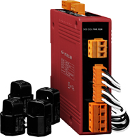
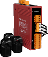
ICP DAS brings the most powerful, cost-effective, advanced Smart Power Meters PM-3000 series that gives you access to real-time electric usage for three-phase power measurement. With its high accuracy (<0.5%, PF=1 ), the PM-3000 series can be applied to both low voltage primary side and/or medium/high voltage secondary side and enables the users to obtain reliable and accurate energy consumption readings from the monitored equipments in real time under operation. These compact size and cost-effective power meters are equipped with revolutionary wired clip-on CT (various types, support input current up to 300 A). It operates over a wide input voltages range 10 ~ 500 VAC which allows worldwide compatibility. And with 2 channels relay outputs, it can be linked with sirens or lightings for alarm messages. It also supports Modbus RTU, Modbus TCP or CANopen protocols for easy integration. You can use CT's that you currently own with PM-3133P (without CTs) Power Meter. The CT inputs of the PM-3133P can handle a maximum of 333mV of AC current.
Feature
- True RMS Power Measurements
- Energy Analysis for 3P4W, 3P3W, 1P3W, 1P2W
- Current Measurements Up to 300 A with Different CT Ratio
- Voltage Measurements Up to 500 V
- Clip-on CT for Easy Installation
- W Accuracy Better than 0.5% (PF=1)
- Supports RS-485, Ethernet (PoE) or CANopen Interface
- Supports Modbus RTU, Modbus TCP or CANopen Protocol
- Supports 2 Power Relay Output (Form A)
- Total Harmonic Distortion (THD)
- IEC 61010-1and EN 61010-1
|
|
|
|
|
|
| CAN Bus Data Logger |
|
|
|
The CAN-Logger series devices (CAN-Logger100 / CAN-Logger200) are high-performance intelligent CAN bus data logger device with one/two CAN port that can help to make data collection and to process on a CAN bus network easier and quicker. The powerful CPU of the CAN-Logger devices provide the accurately time-stamp for each CAN message and supports storage media like SD or SDHC type flash for saving these CAN messages that is useful to analysis and diagnostic the CAN Bus network. In order to enhance the portability of the CAN-Logger200, this module is powered by the USB interface or M12 connectors of CAN bus interface. The CAN-Logger devices use the standard USB HID driver of the Windows system.
Feature
- Compatible with CAN specification 2.0 parts A and B
- 2500 Vrms photocoupler isolation on the CAN side
- Full compatible with the ISO 11898-2 standard
- Supports CAN bus acceptance filter configuration
- Max. CAN data flow for a single channel is 20000 fps
- Programmable CAN bus baud rate from 10 kbps ~ 1Mbps
- USB 2.0 High Speed Compatibility
- Supports 4 to 32 GB SDHC type flash for saving CAN messages
- Built-in jumper for the 120 Ω terminal resistor of the CAN side
- Power by the USB port or CAN port
- 3 kV galvanic isolation for the CAN port
- Provides a configuration utility that can be used to transmit/receive CAN messages
|
|
|
|
|
|
| Software |
|
|
|

CANcheck |
CANcheck is a powerful software package that can be used to verify the functions of any CAN device.
Feature:
- Can set the returned CAN discrimination, eliminating the hassle of wading through logs and manually interpreting results.
- Can be used to operate and diagnose lights, windows, dashboard or other vehicular electronic systems and components.
- The graphical interface is ready-made and easy to operate.
- Supports both the single- and multi-function tests. In multi-function testing, the software provide multi-message sending option.
- Provides the data conversion from the received CAN messages automatically.
- Supports two trends to display the real-time waveform which comes from the CAN messages.
- Provides four free-edited mathematic functions to transfer the raw data instantly and automatically.
|

VxCAN |
The virtual CAN is an integrated library and provides common API functions for all CAN converters and CAN PCI boards.
Feature:
- It can simultaneously access the CAN devices with different hardware interfaces.
- Each application can apply the same APIs to access the CAN network.
- Provide the APIs to search the CAN products within the PC.
- Provide the APIs to access CAN bus through different CAN products.
- Provide VxCAN Utility to operate easily.
|

CAN OPC Server |
By using the NAPOPC.CAN DA server, the software engineers would develop their control systems by the familiar SCADA toolkit and any other software which supports OPC client functionality. |

CAN Test Tool |
The tool tests the following functions simply.
- Two CAN port test to each other
- Test with other CAN device
- Test with CANopen Master/Slave
- Test with DeviceNet Master/Slave
- Test with J1939 Receiver/Transmitter
|
|
|
| |
|
| TOP |
|
| |
|
| |
|
|