home > product> solutions > industrial communication> Fieldbus > CAN Bus
 
I-7531
I-7531-UT
 
Applications
Features
Application Architecture
Driving Capability and Baud Rate
Hardware Specifications
Ordering Information
Optional Accessories
 
 
I-7531 I-7531-UT
  • 繁體中文
  • English
  • CAN bus isolated repeater


    The I-7531/I-7531-UT is an isolated CAN repeater that can be used to establish a physical coupling of two segments of a CAN bus system. This module is designed to isolate the noise and disturbance between the two CAN ports of the I-7531/I-7531-UT. When the CAN signal is decayed because of the rough bus cable or noise, the I-7531/I-7531-UT can recover the shape of the CAN signals to the original ones. Tree topologies can be implemented as well as long drop lines using the I-7531/I-7531-UT. In order to use the I-7531/I-7531-UT easily, the module can automatically adjust the baud rate by itself to match the CAN network. Users just connect the I-7531/I-7531-UT with the CAN buses, check the terminal resistor and power it on, subsequently the I-7531/I-7531-UT enable to work normally.
    For detail information , please refer to the user manual of I-7531/I-7531-UT.


    Applications  
    • Control System
    • Building Automation
    • Factory Automation
    • Distributed data acquisition
     
     
    Features  
    • Compatible with CAN specification 2.0A and 2.0B
    • Fully compatible with the ISO 11898-2 standard
    • Maximum communication baud : 800Kbps
    • 2500 VRMS photo coupler isolation on the CAN side
    • 3KV galvanic isolation among the power supply and 2 CAN ports
    • Jumper for 120Ω terminal resistor of the CAN bus
    • Two CAN channels
    • Auto-baud detection
    • up to 100 nodes on each CAN port
    • Removable terminal block
    • Mount easily on DIN-rail
    Note: We have verified to drive 100 CAN nodes at the same time via one CAN port of I-7531/I-7531-UT.
     
     
    Application Architecture  
     
     
    Driving Capability and Baud Rate  

    The relationship between ideal total bus length and baud are displayed below.

    Baud [bit/sec]
    Ideal Bus Length without I-7531/I-7531-UT [m]
    800K
    50
    500K
    100
    250K
    250
    125K
    500
    50K
    1000
    20K
    2500
    10K
    5000
    Note:
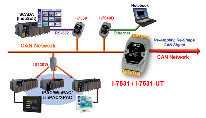
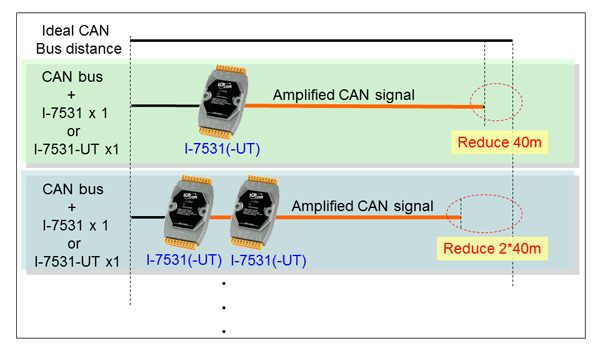
    When users apply one I-7531/I-7531-UT into a CAN network, the ideal CAN communication distance will be reduced 40 meters. For example, if the CAN network is under 500K bps baud rate and one I-7531/I-7531-UT is applied in the network, the ideal total bus length becomes 100-40*1=60 meters. If using two I-7531/I-7531-UTs in this network, the communication distance is 100-40*2=20 meters.

    After deciding the number of I-7531/I-7531-UT and calculating the corresponding ideal bus length, users can use the following table to know the maximum node number in each segment and the maximum segment length when using different type of wire.

    Wire Cross-
    Section [mm2]
    The maximum segment length [m] under the case of
    specific node number in this segment
    32 Nodes
    64 Nodes
    100 Nodes
    ~0.25 (AWG23)
    <200 m
    <170 m
    <150 m
    ~0.5 (AWG20)
    <360 m
    <310 m
    <270 m
    ~0.8 (AWG18)
    <550 m
    <470 m
    <410 m
    ~1.3 (AWG16)
    <900 m
    <780 m
    <670 m
       
    Note:
    The definition of segment and the relationship between segment length (Lseg1, Lseg2 …) and ideal total bus length (Ltotal) are shown in the following figure.


    Hardware Specifications  
    Models I-7531 I-7531-UT
    CAN Interface
    Channel number
    2
    Connector
    3-pin screwed terminal block (CAN_GND, CAN_L, CAN_H)
    Baud Rate (bps)
    5 k ~ 800 k
    Isolation
    3000 VDC for DC-to-DC, 2500 Vrms for photo-couple
    Terminal Resistor
    Jumper for 120 Ω terminal resistor
    Specification
    ISO-11898-2, CAN 2.0A and CAN 2.0B
    Propagation Delay
    200 ns
    Power
    Power supply
    Unregulated +10 ~ +30 VDC
    Protection
    Power reverse polarity protection, Over-voltage brown-out protection
    Power Consumption
    2 W
    Mechanism
    Installation
    DIN-Rail
    Dimensions
    72mm x 118mm x 33mm (W x L x H)
    Environment
    Operating Temp.
    -25 ~ 75 ℃ -40 ~ 85 ℃
    Storage Temp.
    -30 ~ 80 ℃ -45 ~ 90 ℃
    Humidity
    10 ~ 90% RH, non-condensing
     
     
    Ordering Information  
    I-7531-G CAN bus isolated repeater with screw terminal connector
    I-7531-G CR CAN bus isolated repeater with screw terminal connector (RoHS)
    I-7531-UT-G CR CAN bus isolated repeater with screw terminal connector, -40 to 85°C operating temperature (RoHS)
     
     
    Optional Accessories  
    CA-0910-C 9-pin Female D-sub & 3-wire CAN bus cable (1M)
    SG-770 7/14 channel Surge Protector
    4PCD-002 EMI Ferrite Split/Snap-On Core
    M12A-5P-IP68 Field-Installation A-coded 5-pin Female
     
       
    TOP  


    這個頁面上的內容需要較新版本的 Adobe Flash Player。

    取得 Adobe Flash Player