CAN (Controller Area Network) is a serial bus system especially suited to structure intelligent industry devices networks and build smart automatic control systems. The I-7565 is a cost-efficient device for coupling the CAN-bus to the PC using the standard USB interface. Nowadays the interface is present in every new PC and is supported by the MS-Windows 98, Me, 2000 and XP operating systems. If you establish the connection between the I-7565 and the PC during the runtime of the computer, the PC automatically loads the relevant device driver (hot plug & play).
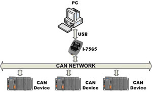
The following figure shows the application architecture for I-7565 modules. The PC can be the CAN host, monitor or HMI to access/control the CAN device through the CAN network by the I-7565 Converter. This module let you to communicate with CAN devices easily from PC with USB interface.
3000V isolation on CAN side
The CAN port of I-7565 is an isolated with 3000V isolation. This isolation can protect the local devices from the damage signal coming from CAN network.
Watchdog inside
The I-7565 Watchdog is a hardware reset circuit to monitor the I-7565’s operation status. When working in harsh or noisy environment, the I-7565 may be down by the external signal. The circuit may let the I-7565 to work continuously and never halt.
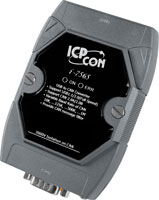
Power and Error indicator display
There are two indicators on the I-7565.The power indicator can help user to check whether the I-7565 is standby or transmitting/receiving messages. The Error indicator will be turned on when some errors occur on the I-7565.
•Factory Automation
•Building Automation
•Home Automation
•Control System
•Monitor System
•Vehicle Automation
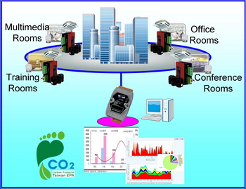
This is the software solution for the CAN bus power meter(PM-213x-CAN). It is convenient to collect the distributed power information via CAN bus. [more...]
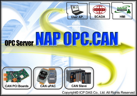
This is the OPC server for all the SCADA like LabVIEW, iFix, DASYLab and etc. By using the OPC server, the users be able to control any CAN devices via the famous SCADA. [more...]
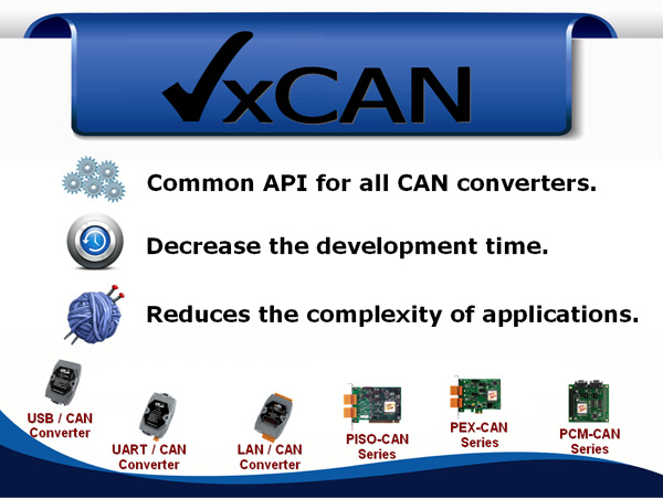
The VxCAN driver is the virtual CAN driver for all CAN converters and CAN master products. Even using different products, the users could use the same APIs to develop any CAN applications. [more...]
The IndoSoft is one of the famous and high performance SCADA. Nowaday, it supports the CAN, CANopen and DeviceNet driver for all the coresponding converter or master series products. [more...]
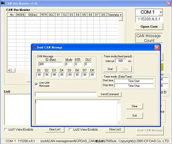
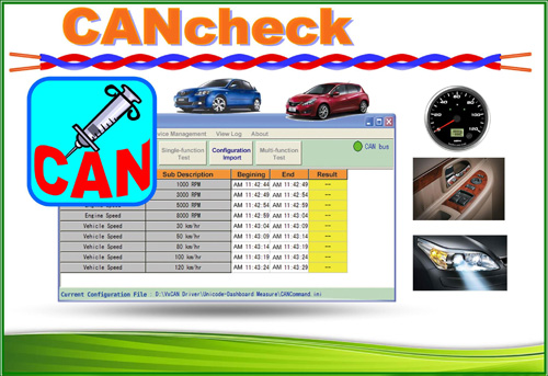
The CAN test tool can help users to test the CAN communication of CAN series of ICP DAS by the simple steps. This tool is based on VxCAN driver and supports most of all CAN products of ICP DAS [more...]