|
|
 |
|
|
PISO-CAN100U-D / PISO-CAN100U-T  ~ NEW ~
1-Port Isolated Protection Universal PCI CAN Card with 9-Pin D-Sub Connector ~ NEW ~
1-Port Isolated Protection Universal PCI CAN Card with 9-Pin D-Sub Connector
1-Port Isolated Protection Universal PCI CAN Card with 5-Pin Screw Terminal Connector |
|
|
| |
| |
|
|
|
|
| |
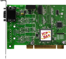
PISO-CAN100U-D
|
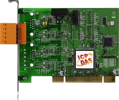
PISO-CAN100U-T
|
|
|
|
|
| |
The CAN (Controller Area Network) is a serial communication protocol, and efficiently supports distributed real-time control with a very high level of security. It is an especially suit for networking "intelligent" devices as well as sensors and actuators within a system or sub-system. In CAN networks, there is no addressing of subscribers or stations in the conventional sense, but instead prioritized messages are transmitted. As standalone CAN controller, PISO-CAN100U-D/T can represent an economic solution of an active CAN board. It has one CAN bus communication port with 5-pin screw terminal connector or 9-pin D-sub connector, and has the ability to cover a wide range of CAN applications. Besides, PISO-CAN100U-D/T uses the new CAN controller Phillips SJA1000T and transceiver 82C250/251, which provide bus arbitration, error detection with auto correction and re-transmission function. It can be installed in a 5V PCI slot and supported truly “Plug & play”. |
|
|
|
|
|
| |
|
|
| |
|
|
| |
• CAN bus communication application.
• DeviceNet, CANopen, CAN J1939, SDS(System Wide Network) protocol application.
• Control System
• Building Automation
• Factory Automation
• Distributed data acquisition
|
| |
|
|
|
| |
|
| |
|
| |
-
One CAN bus communication port
-
Compatible with CAN specification 2.0 parts A and B
-
On-board optical isolation protection
-
Programmable transfer rate up to 1 Mbps
-
2500 Vrms photo couple isolation on the CAN bus
-
Jumper select 120Ω terminator resistor for each port
-
Direct memory mapping to the CAN controllers
-
33MHz 32bit 5V PCI bus (V2.1) plug and play
-
Universal PCI card, supports both 5V and 3.3V PCI bus
Note: We have verified to drive 100 CAN nodes at the same time via one CAN port of PISO-CAN100U. |
| |
|
|
|
| |
|
|
| |
|
|
| |
|
|
| |
|
|
|
|
|
| |
|
|
| |
|
|
| |
|
|
| |
|
|
|
|
|
| |
|
|
| |
|
|
| |
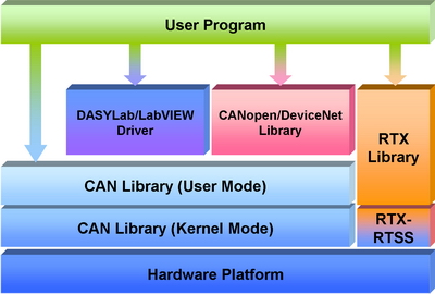
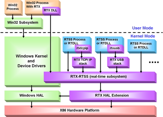
In order to satisfy the users to apply the RTX system, ICPDAS provides the RTX driver for PISO-CAN series CAN card. If users want to combine the CAN communication interface in their time-critical system, the RTX driver of the PISO-CAN series CAN cards can help them to do this easily and quickly. Furthermore, the name and parameters of the APIs in the RTX driver are the same as in the Windows driver. Users don’t need to pay more efforts to study how to use the APIs of the RTX driver if they have used the Windows driver before. The RTX driver increases the additional worth of the PISO-CAN series CAN cards, and satisfies the users to get the highly real-time system. By owing to the feature of high price performance and highly real-time, PISO-CAN series CAN cards will be applied in more wide and more variant CAN applications.
Features:
-
The name and parameters of the APIs in RTX driver are the same as them in the Windows driver. Users don’t need to learn the new usage if they have used the PISO-CAN series CAN card before
-
If the PISO-CAN series CAN card can get the independent IRQ, it supports interrupt function
-
Direct I/O control and highly real-time feature
-
Support Windows2000 SP4, and Windows XP SP2 OS
-
Support RTX version 8.1 and 2011
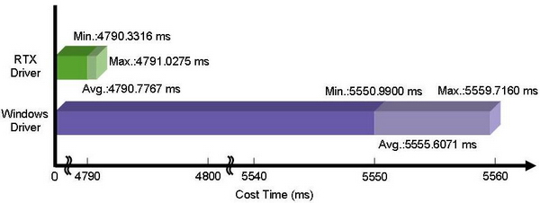
Real-time Test:
-
Platform: Windows XP SP2+PEX-CAN200i
-
Device: I-7186EXD-CAN with MiniOS7 (single tasking OS)
-
Send and receive 10000 CAN 2.0B 8-byte messages. Repeat this procedure for 10 times
|
|
| |
|
|
|
|
|
| |
 |
|
| |
|
|
| |
The SocketCAN is based on the Linux operating system, and it contains the implementation interface of the network stack and the hardware driver. The hardware manufacturers program the hardware driver for the SocketCAN, and the network stack provides the standard BSD Socket APIs for users. Therefore, from the users’ point of view, they can easily and quickly program their applications without being familiar with the various APIs of the different hardware interface through the SocketCAN network stack.
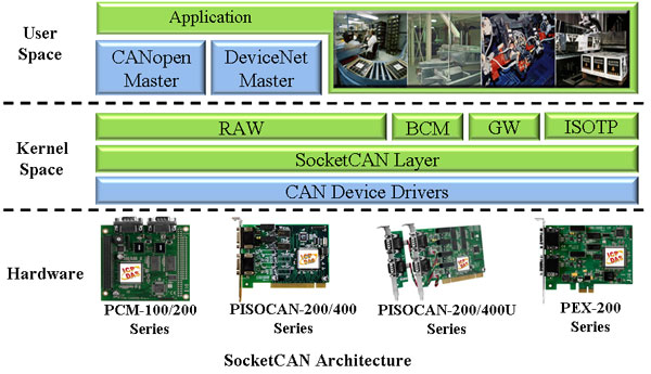
We have provided the SocketCAN drivers for several kinds of CAN interface cards. Users can implement their SocketCAN-based application on the Linux platform by using these cards. Besides, we also support static library of CANopen/DeviceNet master on x86 hardware platform. It can help users communicate with CANopen/DeviceNet slaves more easily.
Features:
-
Support Linux kernel version 2.6.31~3.2.20 (x86 hardware platform only)
-
Provide CANopen/DeviceNet master static library
-
Standard interface for SocketCAN package. Users can use extended BSD socket APIs, you can program the CAN application as building a socket program
-
Support Virtual CAN interface. Users can map several virtual CAN port into one physical CAN port. Each virtual CAN port has its own socket. Through these sockets, users can build the multi-thread application more easily
-
Provide the RAW socket, CANopen master and DeviceNet master demos
-
Good price-performance for economical applications
Hardware platform:Intel(R) Core(TM)2 CPU 6320 @ 1.86GHz, DDR2 667MHz 1.5GB
Software platform:Kernel-2.6.32, Distro- Debian GNU/Linux 5.0
|
|
| |
|
|
|
|
|
| |
|
|
| |
|
|
| |
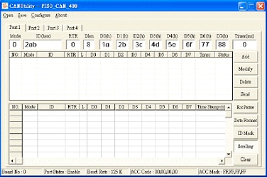
-
Can be a CAN system monitor tool with CAN cards
-
It is a good tool to test CAN system
-
Send/Receive/Record CAN messages
-
Provide cyclic transmission function
-
Record the CAN messages with filtered ID and time stamp
-
Support: 2000/XP/7
|
|
| |
|
|
|
|
|
| |
|
|
| |
|
|
| |
In order to apply the PISO-CAN100U to CAN network with NI LabVIEW, we provides a LabVIEW 7/7.1 toolkit for the purpose. It is a useful tool to develop the CAN-relative application in NI LabVIEW environment by using PISO-CAN100U. It is easy to use and can help user to rapidly reduce their program development cycle. If users want to develop a LabVIEW industrial application with CAN network, the LabVIEW CAN driver is very helpful.
- Support extension arbitration id
- Support debug receive mode
- Start byte of output
- Support LabVIEW 7/7.1
- Scaling range to select
- Two languages, German and English
- Selectable data rates (baud): 10K, 20K, 50K, 125K, 250K, 500K, 800K, 1M, and user defined
|
| |
|
|
|
|
|
| |
|
|
| |
|
|
| |
In order to apply the CANopen protocol on the PISO-CAN100U easily, we provides two CANopen application Tools, which are CANopen library and CANopen diagnosis application tool. If users want to develop an industrial application with CANopen protocol, the CANopen library is very helpful to be applied with the PISO-CAN100U as the CANopen devices with the features of CANopen protocol. Besides, if the monitor and diagnosis of CANopen message on the CAN network is considered, the CANopen diagnostic application tool can be used to achieve this purpose.
- Follow DS301 version 4.02
- Auto detecting CANopen slave devices
- IO monitor
- Dynamic PDO
- NMT master
- Support the Guarding and Heart beat protocol and SYNC message
- Selectable data rates (baud): 10K, 20K, 50K, 125K, 250K, 500K, 800K, 1M
More detail information‥‥
|
|
| |
|
|
|
|
|
| |
|
|
| |
|
|
| |
DeviceNet is a low level network that provides connections between simple industrial devices (sensors, actuators) and higher level devices (controllers). It allows direct peer to peer data exchange between nodes in an organized and, if necessary, deterministic manner. We provides DeviceNet library for users to develop the specific DeviceNet application by PISO-CAN100U. In addition, we also provide the DeviceNet diagnosis application tool to monitor and diagnose the DeviceNet message through CAN network. It provides the DeviceNet communication protocol interface to control and analysis the DeviceNet slaves.
- Auto detecting DeviceNet slave devices
- IO monitor
- Message monitor & diagnosis
- Support UCMM capable devices
- Support the Predefined Master/Slave connection set
- Selectable data rates (baud): 125K, 250K, 500K

More Info‥‥
|
|
| |
|
|
|
|
|
| |
|
|
| |
|
|
| |
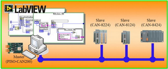
In order to implement DeviceNet communication by NI LabVIEW software, ICPDAS provides a set of DeviceNet component for LabVIEW- “ICPDAS-DNET”. We also have the configuration utility to configure the ICPDAS’s DeviceNet hardware in your PC. The users not only operate easily and develop application rapidly, but also reduce the complexity of applications. The users can communicate with the remote DeviceNet devices in a few simple steps and need not to know about the detail of the DeviceNet protocol. It is a very useful tool to develop the DeviceNet application in NI LabVIEW environment by using ICPDAS-DNET. After finishing install the tool, we offer many basic and advance demo programs for users to reduce the development time. If you are new engineer to develop DeviceNet application, you can refer to the demo programs first. It is the best tool to develop various distributed systems and other industrial application software on DeviceNet network.
-
Auto detecting DeviceNet slave devices
-
DeviceNet I/O monitor
-
Programmable MAC ID Setting
-
Provide hardware configuration tool
-
Support UCMM capable devices
-
Selectable data rates (baud): 125K, 250K, 500K
-
Support the Predefined Master/Slave connection set
|
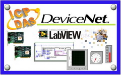 |
- NI LabVIEW Software V7.0 or newer
- NI-DNET DeviceNet driver V1.5 or newer
|
|
| |
|
|
|
|
|
| |
|
|
| |
|
|
| |
Linux kernel version of distributions |
Linux kernel Distribution |
2.6.37 |
Debian GUN/Linux |
4.0 |
Fedora Core |
2/3/4/5/6/7/8 |
Mandrake(Mandriva) |
10.0/10.1/10.2 |
Red Hat Enterprise |
4/5 |
Ubuntu |
7.04 |
SUSE |
9.1/9.2/9.3/10.0 |
Note:We suggest user to use SocketCAN Driver (IxCAN) for Linux kernel Distribution v2.6.25 or later. |
|
| |
|
|
|
|
|
| |
|
|
| |
|
|
| |
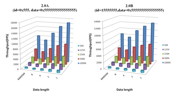
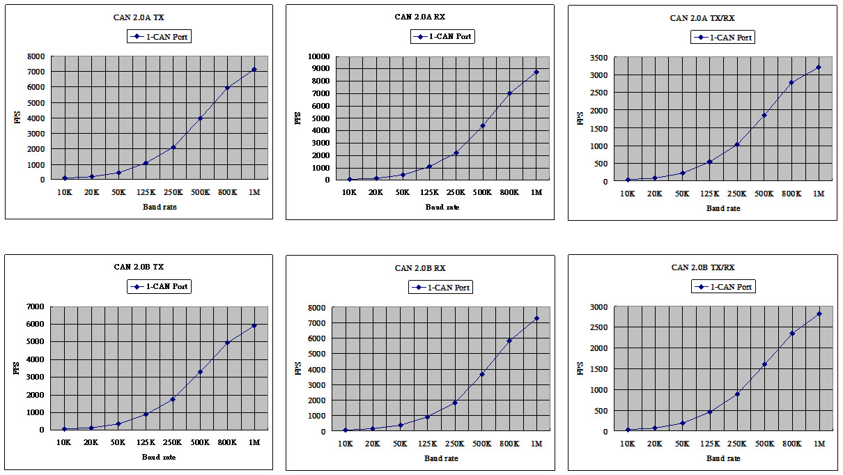
Platform:
OS:Windows XP SP 3
CPU:Intel(R) Core(TM) i3 CPU 550 @ 3.20GHz
RAM:1.8GB
The 1 CAN port send, receive or send/receive 100,000 CAN messages at the same time. The average FPS values are shown below:
| Baud rate (bps) |
1-CAN Port |
| 2.0A, 8 bytes data |
2.0B, 8 bytes data |
| TX (FPS) |
RX (FPS) |
TX/RX (Times/Sec) |
TX (FPS) |
RX (FPS) |
TX/RX (Times/Sec) |
| 10K |
88 |
88 |
43 |
73 |
73 |
37 |
| 20K |
176 |
176 |
87 |
146 |
146 |
75 |
| 50K |
440 |
441 |
218 |
365 |
367 |
188 |
| 125K |
1088 |
1104 |
537 |
899 |
917 |
461 |
| 250K |
2100 |
2208 |
1025 |
1745 |
1834 |
882 |
| 500K |
3975 |
4414 |
1856 |
3305 |
3668 |
1612 |
| 800K |
5930 |
7008 |
2787 |
4950 |
5830 |
2355 |
| 1M |
7129 |
8722 |
3216 |
5926 |
7257 |
2820 |
|
|
| |
|
|
|
|
|
| |
|
|
| |
|
|
| |
| Item |
Description |
CAN bus Power Meter |
This is the software solution for the CAN bus power meter(PM-213x-CAN). It is convenient to collect the distributed power information via CAN bus. [more...] |
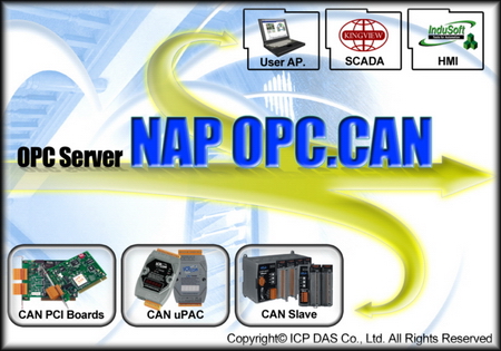
CAN OPC Server |
This is the OPC server for all the SCADA like LabVIEW, iFix, DASYLab and etc. By using the OPC server, the users be able to control any CAN devices via the famous SCADA. [more...] |
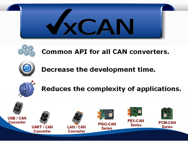
VxCAN Driver |
The VxCAN driver is the virtual CAN driver for all CAN converters and CAN master products. Even using different products, the users could use the same APIs to develop any CAN applications. [more...] |

InduSoft Driver |
The IndoSoft is one of the famous and high performance SCADA. Nowaday, it supports the CAN, CANopen and DeviceNet driver for all the coresponding converter or master series products. [more...] |
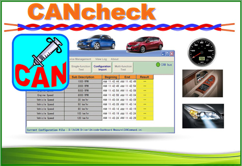
CANcheck |
This is the software for diagnosing and testing the user's CAN devices. The graphical interface is ready-made and easy to operate. [more...] |
CAN Test Tool |
The CAN test tool can help users to test the CAN communication of CAN series of ICP DAS by the simple steps. This tool is based on VxCAN driver and supports most of all CAN products of ICP DAS [more...] |
|
|
| |
|
|
|
|
|
| |
|
|
| |
|
|
| |
Model Name |
PISO-CAN100U-D |
PISO-CAN100U-T |
Bus Interface |
Type |
Universal PCI, 3.3 V and 5 V, 33 MHz, 32-bit, plug and play |
CAN Interface |
Controller |
NXP SJA1000T with 16 MHz clock |
Transceiver |
NXP 82C250 |
Channel number |
1 |
Connector |
9-pin male D-Sub |
5-pin screwed terminal block |
Baud Rate (bps) |
10 k, 20 k, 50 k, 125 k, 250 k, 500 k, 800 k, 1 M (allow user-defined baud rate) |
Isolation |
3000 VDC for DC-to-DC, 2500 Vrms for photo-couple |
Terminator Resistor |
Jumper for 120 Ω terminator resistor |
Power |
Power Consumption |
225 mA @ 5 V |
Software |
Driver |
Windows 2K/XP/7 (32-bit/64-bit OS), Linux 2.6.x ~ 3.2.20, LabView, DASYLab, InduSoft |
Library |
VB 6.0, VC++ 6.0, BCB 6.0, Delphi 4.0, C#.Net, VB.Net (32-bit DLL) |
Mechanism |
Dimensions |
126mm x 22mm x 85mm (W x L x H) |
Environment |
Operating Temp. |
0 ~ 60 ℃ |
Storage Temp. |
-20 ~ 70 ℃ |
Humidity |
5 ~ 85% RH, non-condensing |
|
|
| |
|
|
|
|
|
| |
|
|
| |
|
|
| |
PISO-CAN100U-D CR |
1-Port Isolated Protection Universal PCI CAN Communication Board with 9-pin D-sub connector (RoHS) |
PISO-CAN100U-T CR |
1-Port Isolated Protection Universal PCI CAN Communication Board with 5-pin Screw Terminal Connector (RoHS) |
|
|
| |
|
|
|
|
|
| |
|
|
| |
|
|
| |
|
CAN bus Connector |
|
9-pin Female D-sub & 3-wire CAN bus cable (1M) |
|
7/14 channel Surge Protector |
|
EMI Ferrite Split/Snap-On Core
|
|
Field-Installation A-coded 5-pin Female
|
|
|
| |
|
|
| |
|
|
|
|