| |
|
|
| |
|
|
| |
DIO-64
32-channel Digital Input & 32-channel Digital Output with Timer/Counter Board |
|
|
|
|
|
|
|
| |
|
|
| |
|
|
| |
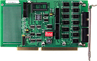
The DIO-64 provides 32 digital input channels , 32 output channels and 6 counter/timer channels The DIO-64 consists of two 16-bit input port and two 16-bit output port . The user can use the DB-16P ( or 782 series ) to. Connect the input port (CN2,CN4) for isolation purpose. The user can use DB-16R (or 785 series) to interface to the output port (CN1,CN3) for relay control. There are four clock source , 2 M , 1 M , 500 k , 250 k, on the board . The user can choose any one by jumper setting .The user can take the frequency from the soldering pad. On board Timer/Counter provides 3-channel for frequency measure , event counting and pulse generation. The optional 8254 provides 3-channel for interrupt use. |
|
|
| |
back |
|
|
|
|
| |
|
|
| |
|
|
| |
- 32 digital input lines
- Buffer output for higher driving capability
- 3 independent programmable 16 bit down counter
- One 16-bit counter , one 32 bit counter with a 4 MHz time base
- Breadboard area for add-on circuit
- Backward compatible to 720 series card
|
|
|
| |
back |
|
|
|
|
| |
|
|
| |
|
|
| |
- Factory automation
- Product test
- Test automation
|
- Digital I/O control
- Alarm monitoring
- 4-channel SSR Output Daughter Board
|
|
|
| |
back |
|
|
|
|
| |
|
|
| |
|
|
| |
- DOS sample program(with source codes)
- DLL and OCX SDK for Windows 98/NT/2000
- DLL and OCX SDK for 32-bit Windows XP/2003/Vista/7
- VB/VC/Delphi/BCB sample programs with source codes are included
- LabVIEW toolkit for Windows
- Driver for Linux and DasyLab
|
|
|
| |
back |
|
|
|
|
| |
|
|
| |
|
|
| |
| Model Name |
DIO-64/3 |
DIO-64/6 |
| Digital Input |
| Channels |
32 |
| Compatibility |
5 V/TTL |
| Input Voltage |
Logic 0: 0.8 V max.
Logic 1: 2.0 V min. |
| Response Speed |
1.0 MHz (Typical) |
| Digital Output |
| Channels |
32 |
| Compatibility |
5 V/TTL |
| Output Voltage |
Logic 0: 0.4 V max.
Logic 1: 2.4 V min. |
| Output Capability |
Sink: 0.8 mA @ 0.8 V
Source: -2.4 mA @ 2.0 V |
| Response Speed |
1.0 MHz (Typical) |
| Timer/Counter |
| Channels |
3 independent |
6 independent |
| Resolution |
16-bit |
| Input Frequency |
10 MHz max. |
| Clock Source |
250 kHz/500 kHz/1 MHz/2 MHz |
| Reference Clock |
Internal: 4 MHz |
| General |
| Bus Type |
ISA |
| I/O Connector |
20-pin box header x 5 |
| Dimensions (L x W x D) |
93 mm x 135 mm x 22 mm |
| Power Consumption |
500 mA @ +5 V |
| Operating Temperature |
0 ~ 60 ¢XC |
| Storage Temperature |
-20 ~ 70 ¢XC |
| Humidity |
5 ~ 85% RH, non-condensing |
|
|
|
|
|
| |
back |
|
|
|
|
| |
|
|
| |
|
|
| |
| DIO-64/3 |
32-channel Digital Input & 32-channel Digital Output,3 Timer/Counter Board |
| DIO-64/6 |
32-channel Digital Input & 32-channel Digital Output,6 Timer/Counter Board |
| DIO-64/3 CR |
32-channel Digital Input & 32-channel Digital Output,3 Timer/Counter Board (RoHS) |
| DIO-64/6 CR |
32-channel Digital Input & 32-channel Digital Output,6 Timer/Counter Board (RoHS) |
|
|
|
|
| |
back |
|
|
|
|
| |
|
|
| |
|
|
| |
| CA-2002 |
20-pin flat cable, 20 cm x 2 |
| CA-2010 |
20-pin flat cable, 20 cm x 2 |
| CA-2020 |
20-pin flat cable 2 M. |
| DB-16P |
16-channel isolated D/I board |
| DB-16R |
16-channel relay board |
| DN-20 |
I/O connector block with DIN-Rail mount |
| DN-20/N |
DN-20 without DIN-Rail mount |
| ADP-20/PCI |
20-pin extender |
| DB-24POR |
24-channel Photo Mos Relay Output Daughter Board |
|
|
| |
|
|
|
|
|
| |
back |
|
| |
|
|
| |
|
|
| |
|
|
| |
|
|
|
|
|
| |
back |
|
| |
|
|