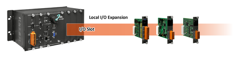
I-9K and I-97K series modules are provided for combining a variety of I/O functions within the WP-9000, XP-9000, LX-9000 and LP-9000 programmable automation controllers (PAC). The I-9K series is based on a parallel interface with high communication speed; while the I-97K series is based on a serial interface.
The differences between the two series are listed as follows:
| Model | I-9K Series | I-97K Series |
|---|---|---|
| Communication interface | Parallel bus | Serial bus |
| Protocol | - | DCON |
| Communication speed | Fast | Slow |
| DI with latched function | - | Y |
| DI with counter input | - | Y (100 Hz) |
| Power on value | Y | Y |
| Safe value | Y | Y |
| Programmable slew-rate for AO module | - | Y |
Features
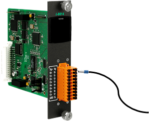
Spring Clamp Terminal Connector
The spring clamp terminal block for the I-9K I/O module connector offers the advantages (anti-vibration, stable clamping and installation easier) relative to screw terminals. Except I-9040/I-9041 modules, the other I-9K modules support spring clamp terminal connector.
The metal part of the cord end terminal on the wire can be direct wired to the terminal.
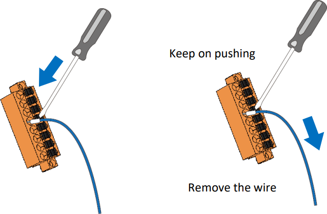
1. Use screwdriver to push the black clip in.
2. Remove the wiring from the terminal block.
I-9K DO Module Power-on Value Function
The digital output power-on value function of the I-9K DO module ensures that the output of the I-9K DO module can be expected and ensures that if the system fails or is reset for any reason, the output will not damage other equipment.
There are 3 power-on modes: deactivated power-on mode, power-on value mode and hold mode. The following is a description of the applicable conditions for each mode. If an exception is encountered that causes boot mode to be activated:
| Mode | Output |
|---|---|
| Power-on Mode Disabled | The DO value will be set to zero |
| Power-on Value Mode | The Power-on value will be used as the DO value when the system is reset |
| Retentive Mode | The previous DO value will be retained |
I-9K DO Safe Value
I-9K DO module equips a Hardware Watchdog (WDT) that monitors the operating status of the module. Its purpose is to prevent problems due to host malfunctions, such as situations where the device is affected by noise, or the program is not stable, etc. When the “refresh WDT” function fails and a Watchdog timeout occurs, all output values on the module will be set to the Safe Value state in order to prevent the controlled target from performing any erroneous operations.

I-9K DI Low Pass Filter
Compared to the I-8K DI module, I-9K DI module has the digital input low pass filter function.
Low-pass filter selectable by hardware or software settings
- Setting by Hardware (1ms/5ms/10ms/20ms/40ms/70ms by Jumper select)
- Setting by Software (Set Jumper position to CPU)
The default low pass filter setting of I-9K DI module is Disable, which can be changed to other modes and set the corresponding output value in DCON Utility or PACSDK API.

| Voltage/Current Input & Output Module
|
|||||||||
|
Voltage/Current Input & Output Module
|
|||||||||
| Model | Analog Input | Analog Output | |||||||
|---|---|---|---|---|---|---|---|---|---|
| I-9K | I-97K | Channel | Resolution | Sampling Rate | Input Range | Channel | Resolution | Output Range | Sink/Source |
| I-9012
(Real Sample and Hold) |
- | 8 | 16-bit | 200/40 kHz | ±5 V, ±10 V |
- | - | - | - |
| I-9014
(Virtual Sample and Hold) |
- | 8/16 | 250/45/25 kHz | ±1.25 V, ±2.5 V, ±5 V, ±10 V, ±20 mA |
|||||
| I-9014C
(Virtual Sample and Hold) |
- | 8 | ±20 mA | ||||||
| I-9017
|
- | 8/16 | 14-bit | 90/16 kHz | ±1.25 V, ±2.5 V, ±5 V, ±10 V, ±20 mA |
- | - | - | - |
| I-9017-15
|
- | 15/30 | |||||||
| I-9017C-15
|
- | 15 | ±20 mA | ||||||
| I-9024
|
- | - | - | - | - | 4 | 14-bit | ±10 VDC, 0 ~ +20 mA |
Sink |
| I-9024U
|
I-97024U
|
16-bit | 0 ~ +5 VDC, ±5 VDC, 0 ~ +10 VDC, ±10 VDC, 0 ~ +20 mA, +4 ~ +20 mA |
Source | |||||
| I-9028U
|
I-97028U
|
8 | |||||||
| Analog Sensor Input Module
|
||||||
|
Analog Sensor Input Module
|
||||||
| Model | Channel | Resolution | Sampling Rate | Input Range | Sensor Input | |
|---|---|---|---|---|---|---|
| - | I-97015
|
8 | 16-bit | 12 Hz | - | Pt100, Pt1000, Ni100, Ni120, Cu50, Cu100, Cu1000 |
| - | I-97017Z
|
10/20 | 50/15 Hz | ±150 mV, ±500 mV, ±1 VDC, ±5 VDC, ±10 VDC ±20 mA ,0 ~ +20 mA, +4 ~ +20 mA |
- | |
| I-9018/S1
|
- | 8 | 100 Hz (per channel) |
- | Thermocouple: J, K, T, E, R, S, B, N, C, L, M, LDIN43710 |
|
| I-9018-16/S1
|
16 | |||||
| - | I-97018/S
|
8 | 10 Hz | ±15 mV, ±50 mV, ±100 mV, ±500 mV, ±1 V, ±2.5 V, ±20 mA |
||
| - | I-97019/S
|
±15 mV, ±50 mV, ±100 mV, ±500 mV, ±1 V, ±2.5 V, ±5 V, ±10 V, ±20 mA |
||||
| DC Digital I/O Module
|
|||||||
|
DC Digital I/O Module
|
|||||||
| Model | DO | DI | |||||
|---|---|---|---|---|---|---|---|
| Channel | Type | Sink/Source (NPN/PNP) |
Max. Load Current @ 25 °C | Channel | Type | Sink/Source (NPN/PNP) |
|
| I-9040P | - | - | - | - | 32 |
Wet, Dry
|
Sink/Source (NPN/PNP) |
| I-9048 | 8 | ||||||
| I-9053P
|
16 | ||||||
| I-9037P | 16 | Open-emitter | Source (PNP) | 700 mA/Channel | - |
-
|
- |
| I-9041P | 32 | Open Collector | Sink (NPN) | 100 mA/Channel | |||
| I-9057P
|
16 | ||||||
| I-9054P | 8 | 500 mA/Channel | 8 | Wet, Dry | Sink/Source (NPN/PNP) |
||
| Relay Output & Digital Input Module
|
|||||||
|
Relay Output & Digital Input Module
|
|||||||
| Model | Relay Output | DI | |||||
|---|---|---|---|---|---|---|---|
| Channel | Relay | Type | Max. Load Current | Channel | Type | Sink/Source (NPN/PNP) |
|
| I-9064 | 8 | Power Relay | Form A | 5 A/channel | - | - | - |
| I-9069 | PhotoMOS Relay | 1 A/channel | |||||
| Encoder Input Module
|
|||||||
|
Encoder Input Module
|
|||||||
| Model | Encoder Input | Compare Trigger Output | |||||
|---|---|---|---|---|---|---|---|
| Axis | Encoder | Resolution | Counting Rate | Hardware Latch/Reset | Channel | Type | |
| I-9093
|
3 | CW/CCW Pulse/Dir |
32-bit | 6 MHz Max. | 3 | 3 | Open Collector |
| AB Phase | 2 MHz Max. | ||||||
| Motion Control Module
|
|||||||||||
|
Motion Control Module
|
|||||||||||
| Model | General | Pulse Output | Encoder Input | Axis I/O | Digital I/O | Interpolation | |||||
|---|---|---|---|---|---|---|---|---|---|---|---|
| Axes | Rate | Counter Width | Counting Rate | Servo Interface | Compare Output |
Latch Input |
Channels | Circular | Helical | Linear | |
| I-9094F
|
4 | 4 MHz (Max.) | 32-bit | 4 MHz (Max.) | Input: INP, ALM Output: SVON |
10 KHz (X and Y only) |
- | Expandable: 128 DI, 128 DO |
Any 2 axes | - | Any 2 to 3 of 4 axes |
| I-9094
|
- | ||||||||||
| I-9196F
|
6 | 12 MHz (Max.) | Input: INP, ALM, RDY Output: SVON, ALM_RST, ERC |
High Speed |
High Speed |
Local: 12 DI, 3 DO Expandable: 128 DI, 128 DO |
Any 2 to 3 of 6 axes | Any 3 of 6 axes | Any 2 to 6 of 6 axes | ||
|
|
||||
|
Communication Module
|
||||
| Model | Interface | Baud Rate | Isolation | |
|---|---|---|---|---|
| Port | Type | |||
| I-9114i
|
4 | RS-232 | 115200 bps Max. | Yes |
| I-9144i
|
RS-422/485 | |||
| I-9174
|
FRnet | 1 Mbps Max. | - | |
|
|
||||
|
HART Module
|
||||
| Model | Port | Protocol | Baud Rate | Isolation |
|---|---|---|---|---|
| I-9720
|
2 | HART | 1200 bps | UL1577 spec. |
|
|
||||
|
CAN Bus Module
|
||||
| Model | Channel | Protocol | Baud Rate | Specification |
|---|---|---|---|---|
| I-9120
|
1 | DeviceNet, CANopen, CAN, J1939 | 10 k, 20 k, 50 k, 125 k, 250 k, 500 k, 800 k, 1 M | ISO-11898-2, CAN 2.0A and CAN 2.0B |