CAN Bus
    I-7531


    CAN Bus
 
 
    I-7000 Series


I-7531 ~ NEW ~
CAN bus isolated repeater


The I-7531 is a CAN repeater used to establish a physical coupling of two or more segments of a CAN bus system. Users can implement tree or star topologies as well as the long drop lines with the I-7531. Users can also increase the maximum number of bus nodes by using the I-7531.

The I-7531 is an optically isolated CAN repeater which provides 2500Vrms of optical isolation. This feature helps you to separate and protect critical segments of the system from the rest of the CAN network. And its galvanic protection isolates among two both CAN segments and the power supply.


The CAN connection of I-7531 is by terminal blocks. A power supply of 10VDC ~ 30VDC is required. I-7531 is housed in a rugged DIN-Rail mountable box, making it easy to install in an industrial cabinet. 
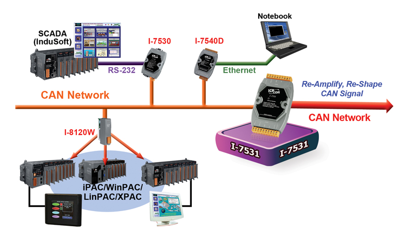
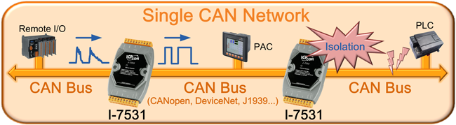
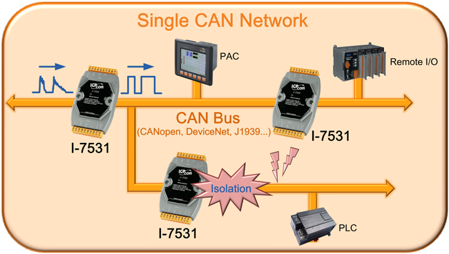
Futhermore, I-7531 can be used in CANopen, DeviceNet and generic ISO 11898-2 standard.

For detail information , please refer to the user manual of I-7531.


• Control System• Building Automation• Factory Automation• Distributed data acquisition


  • Compatible with CAN specification 2.0A and 2.0B
  • Fully compatible with the ISO 11898-2 standard
  • Maximum communication baud : 800Kbps
  • 2500 VRMS photo coupler isolation on the CAN side
  • 3KV galvanic isolation among the power supply and 2 CAN ports
  • Jumper for 120£[ terminator resistor of the CAN bus
  • Two CAN channels
  • Auto-baud detection
  • up to 100 nodes on each CAN port
  • Removable terminal block
  • Mount easily on DIN-rail

Note: We have verified to drive 100 CAN nodes at the same time via one CAN port of I-7531.


The relationship between ideal total bus length and baud are displayed below.

Baud [bit/sec]
Ideal Bus Length without I-7531 [m]
Max I-7531 Number
800K
50
1
500K
100
2
250K
250
6
125K
500
12
50K
1000
25
20K
2500
62
10K
5000
125
   

Note:

When users add one I-7531 into a CAN network, the ideal total bus length will reduce 40 meters because of the propagation delay of I-7531. For example, if users use baud 500K and one I-7531, the ideal total bus length will be 100-40*1=60 meters.

After deciding the number of I-7531 and calculating the corresponding ideal bus length, users can use the following table to know the maximum node number in each segment and the maximum segment length when using different type of wire.

Wire Cross-
Section [mm2]
The maximum segment length [m] under the case of
specific node number in this segment
32 Nodes
64 Nodes
100 Nodes
~0.25 (AWG23)
<200 m
<170 m
<150 m
~0.5 (AWG20)
<360 m
<310 m
<270 m
~0.8 (AWG18)
<550 m
<470 m
<410 m
~1.3 (AWG16)
<900 m
<780 m
<670 m
   

Note:

The definition of segment and the relationship between segment length (Lseg1, Lseg2 ¡K) and ideal total bus length (Ltotal) are shown in the following figure.


CAN Interface
Transceiver
NXP 82C250
Channel number
2
Connector
3-pin screwed terminal block (CAN_GND, CAN_L, CAN_H)
Baud Rate (bps)
5 k ~ 800 k
Isolation
3000 VDC for DC-to-DC, 2500 Vrms for photo-couple
Terminator Resistor
Jumper for 120 £[ terminator resistor
Specification
ISO-11898-2, CAN 2.0A and CAN 2.0B
Power
Power supply
Unregulated +10 ~ +30 VDC
Protection
Power reverse polarity protection, Over-voltage brown-out protection
Power Consumption
2 W
Mechanism
Installation
DIN-Rail
Dimensions
72mm x 118mm x 33mm (W x L x H)
Environment
Operating Temp.
-25 ~ 75 ¢J
Storage Temp.
-30 ~ 80 ¢J
Humidity
10 ~ 90% RH, non-condensing


I-7531-G
CAN bus isolated repeater
I-7531-G CR
CAN bus isolated repeater (RoHS)


9-pin Female D-sub & 3-wire CAN bus cable (1M)
7/14 channel Surge Protector


Copyright© ICP DAS Co., Ltd. All Rights Reserved