CAN Bus
    I-2533


    CAN Bus


I-2533
CAN/Fiber Bridge


I-2533 is a local CAN bridge used to establish a connection between two CAN bus system via fiber optic transmission medium. In order to solve the problem between CAN and fiber transmission medium, I-2533 is specially designed for converting the electrical CAN bus signal to fiber optic cables. Not just like I-2532, I-2533 has three more important features.


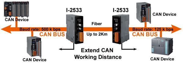
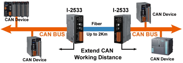
First, the transmission distance limitation of the CAN bus system will not reduced because of CAN baud rate. It means that the total network distance can be extended. Second, the bus error on one CAN network will not affect the operation of another CAN network. Finally, the two CAN network can communication with each other by using different CAN baud rate for highly flexibility. Besides, I-2533 provides the utility tool for user-defined baud rate and filter configuration. By using this tool, it is allowed to have user-defined baud rate and message filter. When users use the I-2533 on two CAN network with different CAN baud rate, it may be useful to reduce the bus loading on the network which has low baud rate.
 
 
2533


• Control System• Building Automation• Factory Automation• Distributed data acquisition


  • 82C250 CAN transceiver
  • 2500 Vrms isolation on the CAN side
  • 3 kv galvanic isolation between the power supply and CAN channel
  • Support both CAN 2.0A and CAN 2.0B specification
  • Fully compatible with the ISO 11898-2 standard
  • Rotary switch for CAN baud rate configuration
  • Built-in switch to select 120£[ terminal resistor
  • Up to 100 CAN nodes on the CAN channel
  • Fiber Port: ST (Multi-mode)
  • Wave Length: 850 nm
  • Transmission distance up to 2 km at any CAN baud rate
  • Provides the 512-record CAN Tx buffer and 512-record CAN Rx buffer
  • Removable terminal block, Mount easily on DIN-rail
  • Allow user-defined baud rate
  • Utility tool for message filter configuration

Note: We have verified to drive 100 CAN nodes at the same time via one CAN port of I-2533.


CAN Interface
Connector
Screwed terminal block (CAN_GND, CAN_L, CAN_H)
Baud Rate (bps)
10 k ~ 1 M
Transmission Distance (m)
Depend on baud rate
Terminator Resistor
Switch for 120£[ terminator resistor
Isolation
3000 VDC for DC-to-DC, 2500 Vrms for photo-couple
Specification
ISO-11898-2, CAN 2.0A and CAN 2.0B
Time Delay
120us max (CAN to fiber or fiber to CAN)
Fiber Interface
Connector
ST (Multi-mode)
Wave Length
850 nm
Fiber Cable
50 / 125 £gm , 62.5 / 125 £gm, 100 / 140 £gm (62.5 / 125£gm is recommended)
Transmission Distance (m)
2 km max (in 62.5 / 125 £gm fiber cable) at any CAN baud rate
LED
Round LED
PWR LED, CAN_Tx LED, CAN_Rx LED, CAN_Err LED, FB_Err LED
Power
Power supply
Unregulated +10 ~ +30 VDC
Protection
Power reverse polarity protection, Over-voltage brown-out protection
Power Consumption
3 W
Mechanism
Installation
DIN-Rail
Dimensions
32.3mm x 77.5mm x 99.0mm (W x L x H)
Environment
Operating Temp.
-25 ~ 75 ¢J
Storage Temp.
-30 ~ 80 ¢J
Humidity
10 ~ 90% RH, non-condensing


2533

Baud [bit/sec]
Ideal Fiber Length [m]
1M
2000
800K
2000
500K
2000
250K
2000
125K
2000
50K
2000
20K
2000
10K
2000


I-2533 CR
CAN/Fiber Converter (RoHS)


EMI Ferrite Split/Snap-On Core
Field-Installation A-coded 5-pin Female


Copyright© ICP DAS Co., Ltd. All Rights Reserved