CAN Bus
    I-2532


    CAN Bus


I-2532
CAN/Fiber Converter


Fiber optic transmission medium is a good material to protect data transmission from EMI/RFI interference and has been used in harsh environment extensively. On the other hand, CAN bus is famous in industrial application. In order to solve the problem between different transmission medium, I-2532 is specially designed for converting the electrical CAN bus signal to fiber optic cables.


The fiber length between two I-2532s can be up to 1.4km (4593ft), it is mainly decided by the cable attenuation of fiber and the CAN bus baud. I-2532 is the economic solution for applications which require protecting the data transmission from electrical exposure, surges, lightning or chemical corrosion.


• Control System• Building Automation• Factory Automation• Distributed data acquisition


  • Compatible with CAN specification 2.0A and 2.0B
  • Fully compatible with the ISO 11898-2 standard
  • Support baud rate up to 500Kbps
  • Jumper for 120£[ terminator resistor of the CAN bus
  • Fiber Port: ST (Multi-mode)
  • Wave Length: 850 nm
  • Auto-baud detection
  • up to 100 nodes on CAN port
  • Removable terminal block
  • Mount easily on DIN-rail


CAN Interface
Connector
8-pin screwed terminal block (CAN_GND, CAN_L, CAN_H, N/A for others)
Baud Rate (bps)
10 k ~ 500 k
Transmission Distance (m)
Depend on baud rate
Terminator Resistor
Switch for 120£[ terminator resistor
Specification
ISO-11898-2, CAN 2.0A and CAN 2.0B
Fiber Interface
Connector
ST (Multi-mode)
Wave Length
850 nm
Fiber Cable
62.5 / 125 £gm
Propagation Delay
125ns max (125ns delay shortens bus line length by ~ 25 m)
Transmission Distance (m)
1.4 km max (in 62.5/125 £gm fiber cable)
LED
Round LED
PWR LED, TD LED, RD LED
Power
Power supply
Unregulated +10 ~ +30 VDC
Protection
Power reverse polarity protection, Over-voltage brown-out protection
Power Consumption
0.5 W
Mechanism
Installation
DIN-Rail
Dimensions
32.3mm x 77.5mm x 99.0mm (W x L x H)
Environment
Operating Temp.
-25 ~ 75 ¢J
Storage Temp.
-30 ~ 80 ¢J
Humidity
10 ~ 90% RH, non-condensing


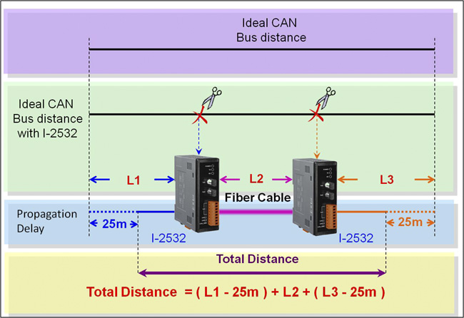
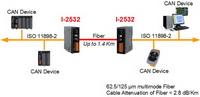
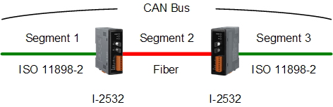
The definition of segment in a CAN bus system are shown as following figure. The segment 2 is fiber cable. Generally, the segment 1 and segment 3 are copper cable. The copper cable is a balanced (differential) 2-wire interface. It may be a Shielded Twisted Pair (STP), Un-shielded Twisted Pair (UTP), or Ribbon cable.

Users can refer to the following table to know the maximum node numbers in each segment following ISO 11898-2 and the maximum segment length when using different type of wire.

Wire Cross-
Section [mm2]
The maximum segment length [m] under the
case of specific node number in this segment
16 Nodes
32 Nodes
64 Nodes
100 Nodes
~0.25 (AWG23)
< 220
< 200
< 170
< 150
~0.5 (AWG20)
< 390
< 360
< 310
< 270
~0.8 (AWG18)
< 590
< 550
< 470
< 410
~1.3 (AWG16)
<980
<900
<780
<670

Higher attenuation of fiber will reduce the transmission distance. Users can use following table to know the relationship between those two.

Attenuation [dB/km]
Fiber Length [m]
2.8
<1400
4
<400

The limitation of baud on a CAN bus system is restricted by propagation delay. On the other hand, long bus length leads to long propagation delay. The relationship between baud and bus length is displayed below.

Baud [bit/sec]
Ideal Bus Length [m]
500K
< 100
250K
< 250
125K
< 500
50K
< 1000
20K
< 2500
10K
< 5000

The definition of segments the relationship between segment length (LSEG1, LSEG2 ¡K) and bus length (LBUS) in the same CAN bus system are shown in the following figure.

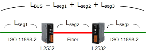
When users add one pair of I-2532 into a CAN bus system, the ideal bus length will reduce 50 meters because the propagation delay of one I-2532 is equal to the propagation delay caused by 25 meters bus length. For example, if users use baud 50Kbps and add two I-2532s into the CAN network, the ideal bus length should less than 950 meters (1000-25*2=950)


I-2532 CR
CAN/Fiber Converter (RoHS)


EMI Ferrite Split/Snap-On Core
Field-Installation A-coded 5-pin Female


Copyright© ICP DAS Co., Ltd. All Rights Reserved