| Models |
μPAC-7186EG(D) |
μPAC-7186PEG(D) |
| System Software |
| OS |
MiniOS7 (DOS-like embedded operating system) |
| Development Software |
ISaGRAF
Software |
ISaGRAF Ver. 3 |
IEC 61131-3 standard |
| Languages |
LD, ST, FBD, SFC, IL & FC |
| Max. Code Size |
64 KB |
| Scan Time |
2 ~ 5 ms for normal program
10 ~ 125 ms (or more) for complex or large program |
| CPU Module |
| CPU |
80186, 80 MHz |
| SRAM |
640 KB |
768 KB |
| Flash |
512 KB |
| EEPROM |
16 KB |
| NVRAM |
31 Bytes (battery backup, data valid up to 10 years) |
| RTC (Real Time Clock) |
Provide second, minute, hour, date, day of week, month, year |
| 64-bit Hardware Serial Number |
Yes, for Software Copy Protection |
| Watchdog Timers |
Yes (0.8 second) |
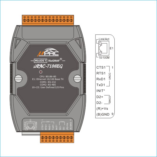
| Communication Ports |
| Ethernet |
RJ-45 x 1, 10/100 Base-TX |
| COM1 |
RS-232 (TxD, RxD, RTS, CTS, GND), non-isolated |
| COM2 |
RS-485 with internal self-tuner ASIC; non-isolated |
| LED Indicator |
| System LED |
Yes (Red) |
Yes (Red/Orange) |
| LED Display |
5-digit 7-segment LED display for (D) version |
| PoE LED Indicator |
- |
Yes (Green) |
| Hardware Expansion |
| I/O Expansion Bus |
Yes, 1 (14 Pins) |
| Mechanical |
| Dimensions (W x L x H) |
72 mm x 123 mm x 35 mm |
| Installation |
DIN-Rail or Wall Mounting |
| Environmental |
| Operating Temperature |
-25 ~ +75 °C |
| Storage Temperature |
-30 ~ +80 °C |
| Ambient Relative Humidity |
10 ~ 90 % RH (non-condensing) |
| Power |
| Input Range |
+10 ~ +30 VDC |
+12 ~ +48 VDC |
| Protection |
Power reverse polarity protection |
| PoE |
- |
IEEE 802.3af, Class 1 |
| Power Consumption |
1.5 W; 2.5 W for (D) version |
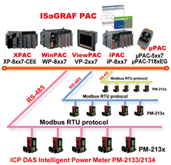
| Protocols (some protocols need optional devices) |
| NET ID |
User-assigned by software, 1 ~ 255 |
Modbus RTU/ASCII Master
Protocol |
Up to 2 COM ports: COM 1 ~ 3 (*). (To connect to other Modbus Slave I/O devices)
Max. Mbus_xxx
Function Block amount for 2 ports: 128. |
Modbus RTU Slave
Protocol |
Up to 2 COM Ports: COM1, one of COM2 or COM3 (*). (For connecting ISaGRAF, PC/HMI/OPC Server & MMI panels) |
Modbus TCP/IP Slave
Protocol |
Ethernet port supports Modbus TCP/IP Slave protocol for connecting ISaGRAF & PC/HMI.
Max. connections: 6. |
| User-Defined Protocol |
COM1, COM2 & COM3 ~ COM8 (*) by serial communication function blocks. |
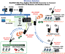
| Remote I/O |
One of COM2 or COM3:RS-485 (*) supports I-7K, I-87K I/O modules as Remote I/O. I-87K series must plug on RU-87Pn (High profile)
or I-87K (Low profile) I/O Unit.
Max. 64 I/O modules for one PAC. |
| Fbus |
Built-in COM2 Port to exchange data between ICP DAS's ISaGRAF controllers. |
| Ebus |
To exchange data between ICP DAS's ISaGRAF Ethernet controllers via Ethernet port. |
| Send Email |
Send Email to maximum 10 receivers each time via internet. If applying with an X607/608 X-board, it could send Email with one attached file and the maximum file size is about 488 KB (using X608) or about 112 KB (using X607). |
SMS:
Short Message Service |
One COM port (one of COM1 or COM3 or COM4) (*) can link to a GSM modem to support SMS. User can request data/control the controller by cellular phone. The controller can also send data & alarms to user's cellular phone.
Optional GSM modems: GTM-201-RS232 (GSM/GPRS 850/900/1800/1900) |
| Modem Link |
Support PC remotely download & monitor the controller through COM4 of X504. (*) |
| MMICON/LCD |
COM3: RS-232 (*) supports ICP DAS's MMICON. The MMICON is featured with a 240 x 64 dot LCD and a 4 x 4 Keyboard. User can use
it to display picture, string, integer, fl oat, and input a character, string, integer and fl oat. |
| Redundancy Solution |
One is Master, one is Slave. Master handles all inputs & outputs at run time. If Master is damaged (or Power off), Slave takes the control of Bus7000b. If Master is alive again, it takes the control of Bus7000b again. The change over time is about 5 seconds. Control data is exchanging via Ebus (if using a cross cable, there is no need of any Ethernet switch). All I/O should be RS-485 I/O except the status I/O in the slot 0: X107. |
| CAN/CANopen |
Use COM1 or COM3 ~ COM8 (*) to connect one I-7530: the RS-232 to CAN converter to support CAN/CANopen devices/sensors. One PAC supports Max. 3 RS-232 ports to connect Max. 3 I-7530 modules. (FAQ-086) |
| Optional I/O Functions (Refer to ISaGRAF PAC I/O Selection Guide for I/O Module list) |
| PWM Output |
| Pulse Width Modulation Output |
All X-board series DO boards support PWM output. 8 channels Max. for one controller.
500 Hz max. for Off = 1 & On = 1 ms
Output square wave: Off: 1 ~ 32767 ms, On: 1 ~ 32767 ms |
| Counters |
| Parallel DI Counter |
All X-board series DI boards support DI counter.
8 channels. Max. for one controller. Counter value: 32-bit,
500 Hz
Max. Min. ON & OFF width must > 1 ms |
| Remote DI Counter |
All remote I-7K/I-87K DI modules support counters. 100 Hz Max. value: 0 ~ 65535 (16-bit) |
| Remote High Speed Counter |
I-87082: 100 kHz Max., 32-bit |
| SRAM Expansion |
| Battery Backup SRAM |
With an X607/X608 plug in the only expansion I/O slot. Data can be stored in X607/X608, and then PC can load these data via COM1 or Ethernet. PC can also download pre-defined data to the X607/X608. (for retain variables) Optional: X607: 128 KB, X608: 512 KB |
*Note: COM3 ~ COM8 are resided at the optional X-board series if it is plugged inside the μPAC-7186EG/PEG.
* ISaGRAF FAQ: http://www.icpdas.com/faq/isagraf.htm
* Recommend to use NS-205/NS-208 Industrial Ethernet Switch. |