|
|
| |
|
|
|
|
| |
|
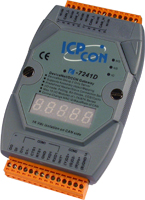
I-7242D 
DeviceNet / Modbus RTU Gateway |
|
|
|
|
|
|
|
| |
|
|
| |
The I-7242D is
one of CAN bus products in ICP DAS. The device allows a master
located on a DeviceNet network to enter into a dialogue with the
slaves on a Modbus RTU network In DeviceNet network, it is a Group 2 Only Slave device, and supports “Predefined Master/Slave
Connection Set”.
|
|
| |
It is a general protocol converter operating
in a way that is transparent to the user. In addition, we also
provide the utility software for users to configure the I-7242D,s
parameters and build the EDS file. Users can easily apply Modbus
RTU devices in DeviceNet applications with the I-7242D. |
 |
|
|
| |
|
| |
|
| |
• Control System•
Building Automation• Factory Automation• Distributed
data acquisition
 |
| |
|
|
|
| |
|
|
| |
|
|
| |
|
| |
-
Group two only server DeviceNet
subscriber
-
Dynamic Assembly Objects Mapping
-
On-line change baud rate and MAC ID of CAN
-
NS, MS and IO LED indicators
-
7-segmemt LED to show operation mode, MAC ID,
baud rate and error code
-
Connection supported:
1
“Explicit Connection”
1
“Polled Command/Response” connection
1”Bit-Strobed
Command/Response” connection
1”Change-of-State / Cyclic”
connection
-
Configuration facilitated by the use of specific
EDS files
-
Dedicated Explicit message interface for full
Modbus interface
-
Explicit & I/O length: 240 bytes max.
|
| |
|
|
| |
|
|
| |
-
Maximum number of subscribers:
10 Modbus commands
-
Communication speed: 1200,2400,4800,9600,19200,38400,57600
or 115200 bits/s, configured using Utility.
-
Data bits: 8 bits, configured using Utility
-
Parity bits: None, even or odd, configured using
Utility
-
Stop bits: 1 or 2 bits, configured using Utility
|
|
| |
|
|
|
|
|
| |
|
|
| |
|
|
The I-7242D Utility is help
users to configure the devices, and has following features: |
-
Support DeviceNet node ID, baud rate
setting
-
Support Modbus RTU parameters setting
-
Show Modbus RTU devices configuration
-
Show DeviceNet application and assembly
objects configuration
-
Support DeviceNet Polling, Bit-Strobe
and COS/Cyclic Produced and Consumed connection path setting
-
Dynamic produce EDS file
|
 |
|
| |
|
|
|
| |
|
| |
|
| |
The simple steps
about how to use DNS_MRU gateway are described as follows:
|
| |
|
|
|
| |
|
| |
|
| |
Code |
Name |
Description |
01 (0x01)
|
Read Coil Status |
Read the ON/OFF status
of discrete outputs in the slave |
02 (0x02) |
Read
Input Status |
Read
the ON/OFF status of discrete inputs in the slave |
03 (0x03) |
Read
Holding Registers |
Read
the binary contents of holding registers in the slaves |
04 (0x04) |
Read
Input Registers |
Read
the binary contents of input registers in the slaves |
15
(0x0F) |
Force Multi Coils |
Forces
each coil in a sequence of coils to either ON or OFF |
16 (0x10) |
Preset
Multi Registers |
Preset value into
a sequence of holding registers |
|
|
| |
|
|
|
|
|
| |
|
|
| |
|
|
| |
Hardware |
Watchdog |
Watchdog IC |
CAN Interface |
Controller |
NXP SJA1000T with 16 MHz clock |
Transceiver |
NXP 82C250 |
Connector |
5-pin screwed terminal block (CAN_L, CAN_H, N/A for others) |
Isolation |
1000 VDC for DC-to-DC, 2500 Vrms for photo-couple |
Protocol |
DeviceNet Volumn I ver2.0, Volumn II ver2.0 |
UART Interface |
COM 1 |
RS-232 (For configuration) |
COM 2 |
RS-485 (Self-turner inside) |
Baud Rate (bps) |
1200, 2400, 4800, 9600, 19200, 38400, 57600, 115200 |
Data bit |
7, 8 |
Stop bit |
1, 2 |
Parity |
None, Even, Odd |
Protocol |
Modbus RTU |
LED |
Round LED |
MS LED, NS LED, IO LED |
5-digit 7 Segment |
Yes |
Power |
Power supply |
Unregulated +10 ~ +30 VDC |
Protection |
Power reverse polarity protection, Over-voltage brown-out protection |
Power Consumption |
3 W |
Mechanism |
Dimensions |
72mm x 122mm x 33mm (W x L x H) |
Environment |
Operating Temp. |
-25 ~ 75 ℃ |
Storage Temp. |
-30 ~ 80 ℃ |
Humidity |
10 ~ 90% RH, non-condensing |
|
|
| |
|
|
|
|
|
| |
|
|
| |
|
|
| |
I-7242D-G
|
DeviceNet Slave / Modbus RTU Master Gateway
|
I-7242D-G CR
|
DeviceNet Slave / Modbus RTU Master Gateway (RoHS)
|
|
|
| |
|
|
|
|
|
| |
|
|
| |
|
|
| |
|
CAN bus Connector |
|
9-pin Female D-sub & 3-wire CAN bus cable (1M) |
|
7/14 channel Surge Protector |
|
EMI Ferrite Split/Snap-On Core
|
|
Field-Installation A-coded 5-pin Female
|
|
|
| |
|
|
| |
|
|