|
|
| |
|
|
|
|
| |
|
GW-7243D
~ NEW ~
DeviceNet Slave / Modbus Master Gateway |
|
|
|
|
|
|
|
| |
|
|
| |
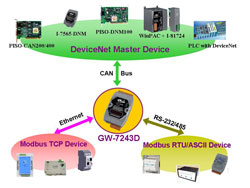
The GW-7243D is one of DeviceNet products in ICP DAS and
it stands as a DeviceNet slave to Modbus TCP/RTU/ASCII master Gateway device.
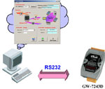
It allows a master located on a DeviceNet network to enter a dialogue with slave devices on the Modbus TCP/RTU/ASCII network. In DeviceNet network, it functions as a Group 2 Only Server device. In Modbus network, GW-7243D represents a master device and sends request message to access the Modbus TCP/RTU/ASCII slave device by DeviceNet object definition. In order to simplify the protocol converting mechanism, we also provide the GW-7243D Utility tool for users to configure the device parameters and build EDS file for the DeviceNet slave device. Users can easily apply Modbus TCP/RTU/ASCII devices in DeviceNet applications through the GW-7243D. The application architecture is depicted as following figure. Users can connect the Modbus TCP/RTU/ASCII devices to the DeviceNet network via the GW-7243D. |
 |
|
|
|
| |
|
| |
|
| |
● Production cell builds and tests CPUs
● Beer brewery
● Equipment for food packing
● Fiberglass twist machine
● Sponge production plant
● Sponge production plant
● Overhead storage bin production
● Pocket-bread bakery |
● Dinnerware production
● HVAC module production
● HVAC module production
● Trawler automation system
● LCD manufacturing plant
● Rolling steel door production
● Bottling line
● Tight manufacturing |
 |
| |
|
|
|
| |
|
|
| |
|
|
| |
|
| |
-
Comply with DeviceNet specification Volume I/II, Release 2.0
-
“Group 2 Only Server” DeviceNet subscriber
-
On-line change baud rate and MAC ID of CAN
-
MS.NS and IO Led indicators
-
Support Offline Connection Set and Device Shutdown Message
-
Explicit & I/O length: 240 bytes max.
-
Connection supported:
one “Explicit Connection”
one “Polled Command/Response” connection
|
| |
|
|
| |
-
User can select the Modbus RTU/ASCII protocol for each COM port
-
Maximum support 10 Modbus RTU/ASCII commands for each COM port
-
Support Modbus function codes: 0x01,0x02,0x03,0x04,0x05,0x06,0x0F and 0x10
-
Support communication speed: 1200、2400、4800、9600、19200、38400、57600 and 115200 bps
-
Data bits: 7 or 8 bits
-
Parity bits: None, even or odd
-
Stop bits: 1 or 2 bits
-
Maximum support 1920 channels DI/O for a Modbus RTU/ASCII command
-
Maximum support 120 channels AI/O for a Modbus RTU/ASCII command
-
Maximum support 2048 channels DI,2048 channels DO,1024 channels AI and 1024 channels AO for each COM port.
|
|
| |
|
|
| |
-
Maximum support 4 Modbus TCP devices
-
Maximum support 5 Modbus TCP commands for each Modbus TCP device
-
Support Modbus function codes: 0x01,0x02,0x03,0x04,0x05,0x06,0x0F and 0x10
-
Maximum support 1920 channels DI/O for a Modbus TCP command
-
Maximum support 120 channels AI/O for a Modbus TCP command
-
Maximum support 2048 channels DI,2048 channels DO,1024 channels AI and 1024 channels AO for each Modbus TCP device.
|
|
| |
|
|
|
|
|
| |
|
|
| |
|
|
The GW-7243D Utility helps users to configure the devices, and has following features:: |
-
Support module IP/Gateway/Mask setting
-
Support DeviceNet node ID, baud rate setting
-
Support Com port communication setting
-
Support Modbus TCP/RTU/ASCII protocol communication parameters setting
-
Support DeviceNet Polling I/O connection path setting
-
Show Modbus TCP/RTU/ASCII protocol communication parameters
-
Show DeviceNet Application Objects configuration
-
Dynamic produce EDS file after setting
|
 |
|
| |
|
|
|
| |
|
| |
|
| |
The simple steps about how to use GW-7243D are described as follows:
 |
| |
|
|
|
| |
|
| |
|
| |
Code |
Name |
Description |
01 (0x01) |
Read Coil Status |
Read the ON/OFF status of discrete outputs in the slave |
02 (0x02) |
Read Input Status |
Read the ON/OFF status of discrete inputs in the slave |
03 (0x03) |
Read Holding Registers |
Read the binary contents of holding registers in the slaves |
04 (0x04) |
Read Input Registers |
Read the binary contents of input registers in the slaves |
05 (0x05) |
Write Singal Coil |
Force a single coil to either ON or OFF |
06 (0x06) |
Write Single Register |
Preset a value into a single holding register |
15 (0x0F) |
Force Multi Coils |
Forces each coil in a sequence of coils to either ON or OFF |
16 (0x10) |
Preset Multi Registers |
Preset value into a sequence of holding registers |
|
|
| |
|
|
|
|
|
| |
|
|
| |
|
|
| |
Hardware |
EEPROM |
16 KB; Data retention: 40 years; 1,000,000 erase/write cycles |
Watchdog |
Watchdog IC |
CAN Interface |
Controller |
NXP SJA1000T with 16 MHz clock |
Transceiver |
NXP 82C250 |
Connector |
5-pin screwed terminal block (CAN_L, CAN_H, N/A for others) |
Isolation |
1000 VDC for DC-to-DC, 2500 Vrms for photo-couple |
Protocol |
DeviceNet Volumn I ver2.0, Volumn II ver2.0 |
UART Interface |
COM 1 |
RS-232 |
COM 1 Connector |
5-pin screwed terminal block (TxD, RxD, RTS, CTS, GND ) |
COM 2 |
RS-485 (Self-turner inside) |
COM 2 Connector |
2-pin screwed terminal block (DATA+, DATA-) |
Protocol |
Modbus ASCII / Modbus RTU |
Ethernet Interface |
Controller |
10/100Base-TX Ethernet Controller (Auto-negotiating, Auto_MDIX) |
Connector |
RJ-45 with LED indicator |
Protocol |
Modbus TCP |
Power |
Power supply |
Unregulated +10 ~ +30 VDC |
Protection |
Power reverse polarity protection, Over-voltage brown-out protection |
Power Consumption |
2.5 W |
Mechanism |
Dimensions |
72mm x 122mm x 33mm (W x L x H) |
Environment |
Operating Temp. |
-25 ~ 75 ℃ |
Storage Temp. |
-30 ~ 80 ℃ |
Humidity |
10 ~ 90% RH, non-condensing |
|
|
| |
|
|
|
|
|
| |
|
|
| |
|
|
| |
GW-7243D-G CR |
DeviceNet Slave / Modbus Master Gateway (RoHS)
|
|
|
| |
|
|
|
|
|
| |
|
|
| |
|
|
| |
|
EMI Ferrite Split/Snap-On Core
|
|
Field-Installation A-coded 5-pin Female
|
|
|
| |
|
|
| |
|
|