|
|
 |
 |
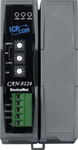
| CAN-8124 |
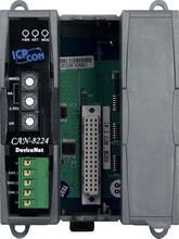
CAN-8224 |
|
|
|
|
DeviceNet is one kind
of the network protocols based on the CAN bus and mainly
used for embedded network for machine control, such as
textile machinery, printing machines, injection molding
machinery, or packaging machines, etc. DeviceNet is a
low level network that provides connections between simple
industrial devices (sensors, actuators) and higher level
devices (controllers). It allows direct peer to peer data
exchange between nodes in an organized and, if necessary,
deterministic manner. DeviceNet defines a connection-based
scheme to facilitate all application communications. A
DeviceNet connection provides a communication path between
multiple endpoints. The endpoints of a connection are
applications that need to share data.
The CAN-8124/CAN-8224 main control unit is specially designed for
the slave device of DeviceNet protocol. It follows the
Specification of DeviceNet. In order to expand I/O channel
more flexible, an CAN-8x24 supports 1/2 slot(s) for I/O expansion
and suits with a lot of ICP DAS DI/AI/DO/AO modules.
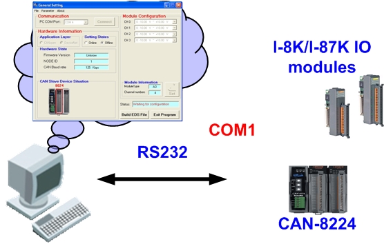
Users
can choice DI/DO/AI/AO modules of I-87K series or I-8000
series to fit the customized practice applications. In addition,
we also provide CAN Slave Utility to allow users to create
the EDS file dynamically. The EDS file is based on DeviceNet
and can be compatible with different DeviceNet master interfaces.
The application architecture is as image on the right.
|
|
|
|
| Utility |
|
|
|
In
the CAN-8124/CAN-8224 device, ICPDAS provides CAN Slave Utility to produce
the specific EDS file with the plugged in modules in off-line
mode. After finishing the utility configuration, it can create
the EDS file. There is also much DeviceNet information of the
CAN-8x24 in the EDS file. It is not only for DeviceNet master
interface but also for users to know more information about the
slave device. Users also can use the default configuration for
general DI/DO/AI/AO. And users only need to set the MAC ID and
Baud rate by hardware rotary switch. Then, after wire connection
and the CAN-8x24 powered on, it can work normally on the CAN bus
network through DeviceNet protocol. |
|
|
|
| Design Flowchart |
|
|
|
The following simple steps show
how to use CAN-8x24 in DeviceNet protocol.
|
|
|
|
| Features |
|
|
|
DeviceNet
Version |
DeviceNet
Specification Volume I & II, Release 2.0 |
Number
of Nodes |
64(Max) |
Baud
Rate |
125K, 250K,
500K |
Support
Message Groups |
Group 2 only
Server |
UCMM |
Not Support |
I/O
Operating Modes |
Poll, Bit-Strobe,
Change of State/ Cyclic |
Device
Heartbeat Message |
ˇ |
Device
Shutdown Message |
ˇ |
Produce
EDS file Dynamically |
ˇ |
No.
of Fragment I/O |
128
Bytes (Max) (Input/ Output) |
MAC
ID Setting |
Rotary
Switch |
Baud
Rate Setting |
Rotary
Switch |
DeviceNet
Status LED |
NET,
MOD, PWR |
|
|
|
|
| Applications |
|
|
|
- Automotive
- Food & Beverage
- Packaging
- High-speed
Assembly
- Pulp & Paper
- Semiconductor Fabrication
- Control System...etc.
|
 |
|
|
|
|
| Hardware Specifications |
|
|
|
|
|
|
Hardware |
CPU |
80186, 80 MHz or compatible |
SRAM/Flash/EEPROM |
512 KB / 512 KB / 16 KB |
NVRAM |
31 bytes (battery backup, data valid for up to 10 years) |
RTC (Real Time Clock) |
Yes |
Watchdog |
Watchdog IC |
Expansion Slot |
1 slots |
2 slots |
CAN Interface |
Controller |
NXP SJA1000T with 16 MHz clock |
Transceiver |
NXP 82C250 |
Channel number |
1 |
Connector |
5-pin screwed terminal block (CAN_GND, CAN_L, CAN_SHLD, CAN_H, CAN_V+) |
Baud Rate (bps) |
125 k, 250 k, 500 k |
Transmission Distance (m) |
Depend on baud rate (for example, max. 500 m at 125 kbps ) |
Isolation |
3000 VDC for DC-to-DC, 2500 Vrms for photo-couple |
Terminal Resistor |
Jumper for 120 Ω terminal resistor |
Specification |
ISO-11898-2, CAN 2.0A |
Protocol |
DeviceNet Volumn I ver2.0, Volumn II ver2.0
Predefined Master/Slave Connection set |
LED |
Round LED |
PWR LED, NET LED, MOD LED |
Power |
Power supply |
Unregulated +10 ~ +30 VDC |
Protection |
Power reverse polarity protection, Over-voltage brown-out protection |
Power Consumption |
1.7 W |
2 W |
Mechanism |
Installation |
DIN-Rail
|
DIN-Rail or Wall Mounting |
Dimensions |
64mm x 119mm x 91mm
(W x L x H) |
95mm x 132mm x 91mm
(W x L x H) |
Environment |
Operating Temp. |
-25 ~ 75 ℃ |
Storage Temp. |
-30 ~ 80 ℃ |
Humidity |
10 ~ 90% RH, non-condensing |
|
|
|
|
| Modules Support |
|
|
|
| CAN-8124 Support Module Table |
|
|
|
| Ordering Information |
|
|
|
| CAN-8124-G |
DeviceNet Embedded Device with 1 I/O Expansion |
| CAN-8224-G |
DeviceNet Embedded Device with 2 I/O Expansions |
|
|
| |
|
| TOP |
|
| |
|
| |
|
|