DeviceNet Slave to Modbus TCP/RTU/ASCII Master Gateway
The GW-7243D offers the DeviceNet slave and Modbus master functions, and enables the DeviceNet master to access the Modbus slave devices. In the DeviceNet network, the module acts as a Group 2 Only Server device, and waits to build the connection with the DeviceNet master. In the Modbus network, the GW-7243D is a master device, and cyclically sends the commands to access the Modbus slave devices. Both the Modbus TCP client and Modbus RTU/ASCII master interfaces of the GW-7243D can work simultaneously. This feature means that users are able to integrate different kinds of Modbus slave devices together into the DeviceNet network no matter these devices provide Ethernet, RS-232 or RS-485 communication interfaces. In order to simplify the use of the GW-7243D, the GW-7243D Utility tool for confi guration and EDS file production is given. This is helpful to build the applications easily and quickly.
Applications
Production cell builds and tests CPUs
Beer brewery
Equipment for food packing
Fiberglass twist machine
Sponge production plant
Sponge production plant
Overhead storage bin production
Pocket-bread bakery
Dinnerware production
HVAC module production
Trawler automation system
LCD manufacturing plant
Rolling steel door production
Bottling line
Tight manufacturing
Features
DeviceNet Features
Comply with DeviceNet specification Volume I/II, Release 2.0
“Group 2 Only Server” DeviceNet subscriber
On-line change baud rate and MAC ID of CAN
MS.NS and IO Led indicators
Support Offline Connection Set and Device Shutdown Message
Explicit & I/O length: 240 bytes max.
Connection supported:
one “Explicit Connection”
one “Polled Command/Response” connection
Modbus RTU Features
User can select the Modbus RTU/ASCII protocol for each COM port
Maximum support 10 Modbus RTU/ASCII commands for each COM port
Support Modbus function codes: 0x01,0x02,0x03,0x04,0x05,0x06,0x0F and 0x10
Support communication speed: 1200、2400、4800、9600、19200、38400、57600 and 115200 bps
Data bits: 7 or 8 bits
Parity bits: None, even or odd
Stop bits: 1 or 2 bits
Maximum support 1920 channels DI/O for a Modbus RTU/ASCII command
Maximum support 120 channels AI/O for a Modbus RTU/ASCII command
Maximum support 2048 channels DI,2048 channels DO,1024 channels AI and 1024 channels AO for each COM port
Modbus TCP Features
Maximum support 4 Modbus TCP devices
Maximum support 5 Modbus TCP commands for each Modbus TCP device
Support Modbus function codes: 0x01,0x02,0x03,0x04,0x05,0x06,0x0F and 0x10
Maximum support 1920 channels DI/O for a Modbus TCP command
Maximum support 120 channels AI/O for a Modbus TCP command
Maximum support 2048 channels DI,2048 channels DO,1024 channels AI and 1024 channels AO for each Modbus TCP device
Utility
The GW-7243D Utility helps users to configure the devices, and has following features:
Support module IP/Gateway/Mask setting
Support DeviceNet node ID, baud rate setting
Support Com port communication setting
Support Modbus TCP/RTU/ASCII protocol communication parameters setting
Support DeviceNet Polling I/O connection path setting
Show Modbus TCP/RTU/ASCII protocol communication parameters
Show DeviceNet Application Objects configuration
Dynamic produce EDS file after setting
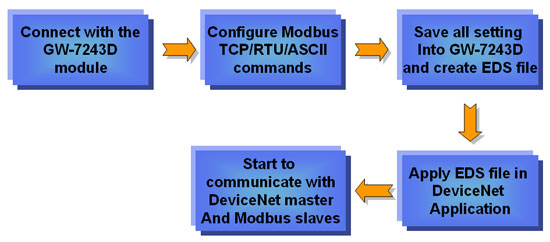
Usage
The simple steps about how to use GW-7243D are described as follows:
Modbus TCP RTU Commands Support
Code
Name
Description
01 (0x01)
Read Coil Status
Read the ON/OFF status of discrete outputs in the slave
02 (0x02)
Read Input Status
Read the ON/OFF status of discrete inputs in the slave
03 (0x03)
Read Holding Registers
Read the binary contents of holding registers in the slaves
04 (0x04)
Read Input Registers
Read the binary contents of input registers in the slaves
05 (0x05)
Write Singal Coil
Force a single coil to either ON or OFF
06 (0x06)
Write Single Register
Preset a value into a single holding register
15 (0x0F)
Force Multi Coils
Forces each coil in a sequence of coils to either ON or OFF
16 (0x10)
Preset Multi Registers
Preset value into a sequence of holding registers
Hardware Specifications
Hardware
EEPROM
16 KB; Data retention: 40 years; 1,000,000 erase/write cycles
Watchdog
Watchdog IC
CAN Interface
Controller
NXP SJA1000T with 16 MHz clock
Transceiver
NXP 82C250
Connector
5-pin screwed terminal block (CAN_L, CAN_H, N/A for others)