| Models |
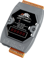
μPAC-7186EG(D) |
μPAC-7186PEG(D) |
| System Software |
| OS |
MiniOS7 |
| Development Software |
| ISaGRAF Version 3 |
IEC61131-3 standard. Languages: LD, ST, FBD, SFC, IL & FC |
| Max. code size |
μPAC-7186EG/PEG accepts max.64 KB ISaGRAF code size (Appli.x8m must < 64KB) |
| Power Supply |
| Input Range |
+10 ~ +30 VDC |
+12 ~ +48 VDC |
| Protection |
Power reverse polarity protection |
| PoE |
No |
IEEE 802.3af, Class 1 |
| Power Consumption |
1.5 W for μPAC-7186EG/PEG
2.5 W for μPAC-7186EGD/PEGD
(when I/O slots are empty) |
| General Environment |
| Temperature |
Operating: -25 ~ +75 °C,
Storage : -30 ~ +80 °C |
| Humidity |
10 ~ 90 % RH (non-condensing) |
| System |
| CPU |
80186 or compatible (16-bit and 80 MHz) |
| Watchdog Timer |
Yes, default 0.8 second |
| RTC (Real Time Clock) |
Provide second, minute, hour, date, day of week, month, year |
| SRAM |
640 KB |
768 KB |
| FLASH Memory |
512 KB, Erase unit is 64 KB, 100,000 erase/write cycles |
| NVRAM |
31 bytes, battery backup, data valid up to 10 years |
| EEPROM |
16 KB (16384 bytes), retention > 100 years. 1,000,000 erase/write cycles |
| Expansion I/O Bus |
One optional X-series I/O board can be plugged inside the μPAC-7186EG/PEG. |
| NET ID |
User-assigned by software, 1 ~ 255 |
Display for
I-7186EGD/PEGD |
5-Digit 7-Seg. LED on the front. It can display message & value. |
| System LED Indicator
|
Yes (Red) |
Yes (Red/Orange) |
| PoE LED Indicator
|
- |
Yes (Green)
|
| Communication Interface
|
| COM1 |
RS-232: TxD, RxD, RTS, CTS, GND Speed: 115200 bps max. Program downloads port ; Non-isolated. |
| COM2 |
RS-485: D+, D-, 115200 bps max. Self-tuner ASIC inside, Program downloads port ; Non-isolated. |
| Ethernet |
10/100 Mbps, NE2000 compatible, 10/100 Base-TX, Programs download port. |
| Dimensions |
| W x H x D |
72 mm x 123 mm x 35 mm |
| PWM Output |
| Pulse Width Modulation Output |
All X-series DO boards support PWM output. 8-ch max. for one controller.
500 Hz max. for Off = 1 & On = 1 ms
Output square wave: Off: 1 ~ 32767 ms, On: 1 ~ 32767 ms |
| Counters |
| Parallel DI Counter |
All X-series DI boards support DI counter.
8-ch. max. for one controller. Counter value: 32-bit
500 Hz max. Min. pulse width > 1 ms |
| Remote DI Counter |
All remote I-7000 & I-87K DI modules support counters. 100 Hz max. value: 0 ~ 65535 |
| Remote High Speed Counter |
Optional I-87082: 100 kHz max. ,32-bit |
| Protocols |
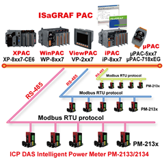
Modbus RTU/ASCII Master
Protocol |
Up to 2 COM Ports (COM1, COM2 and COM3-in-X-board) support Modbus RTU/ASCII Master protocol to connect to other Modbus Slave I/O devices |
Modbus RTU Slave
Protocol |
Up to 2 COM Ports (COM1, one of COM2 or COM3-in-X-board) can support Modbus RTU Slave protocol for connecting ISaGRAF, PC/HMI/OPC Server & MMI panels. |
Modbus TCP/IP
Protocol |
Ethernet port supports Modbus TCP/IP Slave protocol for connecting ISaGRAF & PC/HMI. |
| Remote I/O |
One of COM2 (or COM3: RS-485 if found) supports I-7000 I/O modules & (I-87K base + I-87K serial I/O boards or RU-87P1/2/4/8 + I-87K High Profile I/O cards) as Remote I/O. Max. 64 I/O module for one controller. |
| Fbus |
Built-in COM2 Port to exchange data between ICP DAS's ISaGRAF PACs. |
| Ebus |
To exchange data between ICP DAS's ISaGRAF Ethernet PACs via Ethernet port. |
| Send Email |
Send email to maximum 10 receivers each time via internet. If applying with an X607/608 X-board, it could send email with one attached file and the maximum file size is about 488 KB for using X608 or about 112 KB for using X607. |
SMS:
Short Message Service |
One of (COM1 or COM3: RS-232 or COM4: RS-232 if found) can link to a GSM modem to support SMS. User can request data/control the controller by cellular phone. The controller can also send data & alarms to user's cellular phone.
Optional GSM modems: GTM-201-RS232 ( 850/900/1800/1900 GSM/GPRS External Modem) |
| User-defined Protocol |
User can write his own protocol applied at COM1, COM2 & (COM3 ~ COM8 if found) by serial communication function blocks. |
| Modem Link |
Supports PC to remotely download & monitor the controller through COM4 of X504. |
| MMICON/LCD |
One of (COM3: RS-232 if found) supports ICP DAS's MMICON. The MMICON is featured with a 240 x 64 dot LCD and a 4 x 4 Keyboard. User can use it to display picture, string, integer, float, and input a character, string, integer and float. |
| Redundancy Solution |
One is Master, one is Slave. Master handles all inputs & outputs at run time. If Master is damaged (or Power off), Slave takes the control of Bus7000b. If Master is alive from damaged (or power up again), it takes the control of Bus7000b again. The change over time is about 5 seconds. Control data is exchanging via Ebus (if using a cross cable, no need any Ethernet switch). All I/O should be RS-485 I/O except the status I/O in the slot 0: X-107. |
| CAN/CANopen |
μPAC-7186EG can use its COM1 or COM3 ~ COM8 (resides at the X5xx RS-232 expansion board) to connect one I-7530: the RS-232 to CAN converter to support CAN and CANopen devices and sensors. One μPAC-7186EG supports max.3 RS-232 port to connect max. 3 I-7530. Please refer to oldweb.icpdas.com > FAQ > Software > ISaGRAF Ver.3 (English) > 086 |
| Battery Backup SRAM |
| With the optional X607 or X608 board plugged inside the μPAC-7186EG/PEG, data can be stored in it, and then PC can load these data via COM1 or Ethernet. PC can also download pre-defined data to X607/608. Optional: X607: 128 KB, X608: 512 KB |