| Power Supply |
| Input Range |
+10 ~ +30 VDC, I-7188EG: 2 W, I-7188EGD: 3 W |
| Protection |
Power reverse polarity protection |
| General Environment |
| Temperature |
Operating: -25 ~
+75 °C,
Storage : -30 ~ +80 °C |
| Humidity |
10 ~ 90 % RH (non-condensing ) |
| System |
| CPU |
80188, 40 MHz, or compatible |
| Watchdog Timer |
Yes, default 0.8 second |
| RTC (Real Time Clock) |
Provide second, minute, hour, date, day of week, month, year |
| SRAM |
512 KB |
| FLASH Memory |
512 KB, Erase unit is 64 KB, 100,000 erase/write cycles |
| NVRAM |
31 bytes, battery backup, data valid up to 10 years |
| EEPROM |
2048 bytes, retention > 100 years. 1,000,000 erase/write cycles |
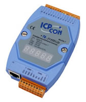
| Display for I-7188EGD |
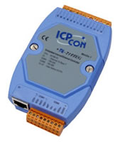
5-Digit 7-Seg. LED on the front. It can display message & value. |
| Expansion I/O Bus |
One optional X-board series I/O board can be plugged inside the I-7188EG/EGD. |
| NET ID |
User-assigned by software, 1 ~ 255 |
| Communication Interface
|
| COM1 |
RS-232: TxD,RxD,RTS,CTS,GND. Speed: 115200 bps max. Program downloads port. |
| COM2 |
RS-485: D+, D-, 115200 bps max. Self-tuner ASIC inside, Program downloads port. |
| Ethernet |
10 Mbps, NE2000 compatible, 10 Base-T. Programs download port |
| Mechanical |
| Dimensions (W x L x H) |
123 mm x 72 mm x 33 mm |
| PWM Output |
| Pulse Width Modulation Output |
All X-board series DO boards support PWM output. 8-ch max. for one controller.
500 Hz max. for Off = 1 & On = 1 ms
Output square wave: Off: 1 ~ 32767 ms, On: 1 ~ 32767 ms |
| Counters |
| Parallel DI Counter |
All X-board series DI boards support DI counter.
8-ch. max. for one controller. Counter value: 32-bit
500 Hz max. Min. pulse width > 1 ms |
| Remote DI Counter |
All remote I-7000 & I-87K DI modules support counters. 100 Hz max. value: 0 ~ 65535 |
| Remote High Speed Counter |
Optional I-87082: 100 kHz max. ,32-bit |
| Protocols |
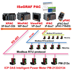
Modbus RTU/ASCII Master
Protocol |
Up to 2 COM Ports (COM1, COM2 and COM3-in-X-board) support Modbus RTU/ASCII Master protocol to connect to other Modbus Slave I/O devices |
Modbus RTU Slave
Protocol |
Up to 2 COM Ports (COM1, one of COM2 or COM3-in-X-board) can support Modbus RTU Slave protocol for connecting ISaGRAF, PC/HMI/OPC Server & MMI panels. |
Modbus TCP/IP
Protocol |
Ethernet port supports Modbus TCP/IP Slave protocol for connecting ISaGRAF & PC/HMI. |
| Remote I/O |
One of COM2 (or COM3: RS-485 if found) supports I-7000 I/O modules & (I-87K base or RU-87P4/8 +
I-87K serial I/O boards) as Remote I/O. Max. 64 I/O modules for one controller |
| Fbus |
Built in COM2 Port to exchange data between ICP DAS's ISaGRAF PACs. |
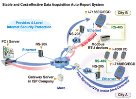
| Ebus |
To exchange data between ICP DAS's ISaGRAF Ethernet PACs via Ethernet port. |
SMS:
Short Message Service |
One of COM1, (COM3: RS-232 or COM4: RS-232 if found) can link to a GSM modem to support SMS. User can request data/control the controller by cellular phone. The controller can also send data & alarms to user's cellular phone.
Optional GSM modems: GTM-201-RS232 (850/900/1800/1900 GSM/GPRS External Modem) |
| User-defined Protocol |
User can write his own protocol applied at COM1, COM2 & (COM3 ~ COM8 if found) by serial communication function blocks. |
| Modem Link |
Supports PC to remotely download & monitor the controller through COM4 of X504. |
| MMICON/LCD |
One of (COM3: RS-232 if found) supports ICP DAS's MMICON. The MMICON is featured with a 240 x 64 dot LCD and a 4 x 4 Keyboard. User can use it to display picture, string, integer, float, and input a character, string, integer and float. |
| Battery Backup SRAM |
I-7188EG/7188EGD can support up to 1024 retain variables with an X607/X608 plug in the only expansion I/O slot. Data can be stored in X607/X608, and then PC can load these data via COM1 or Ethernet. PC can also download pre-defined data to the X607/X608.
Optional: X607: 128 KB, X608: 512 KB |