home > product> solutions > pac > LinPAC > LP-8000 vs. LP-9000/LX-8000/LX-9000 I/O Module Comparison
 
 
LP-8000 vs. LP-9000/LX-8000/LX-9000 I/O Module Comparison


Modules Comparison


Modules Migration
 
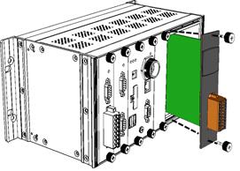
The migration of using LP-8000 platfroms with I-8K/I-87K series modules to LP-9000 platforms with I-9K/I-97K series modules. Some programs and wiring connections may be needed to modify. Refer to the following table for migrating from I-8K/87K modules to I-9K/I-97K modules.
 
I/O modules for LP-8000 platforms
I/O modules for LP-9000 platforms
I-8040W
I-9040
I-8041W
I-9041
I-8114iW
I-9114
I-8144iW
I-9144
 
 
TOP


New Features for I-9K/I-97K modules
 
Spring clamp terminal connector

The spring clamp terminal block for the I/O module connector of LP-9000 offers the advantages (anti-vibration, stable clamping and installation easier) relative to screw terminals.

Except I-9040/I-9041 modules, the other I-9K modules support spring clamp terminal connector.


TOP


The Difference of I-8K/I-87K and I-9K/I-97K modules
 
The height of the I-9K/I-97K module including the terminal block plugged on a LP-9000 controller is 164mm, and the height of I-8K/87K module plugged on LP-8000 controller is 111 mm.
 
(Unit: mm)
 
 
TOP


The Common features of all I-9K/I-97K modules
 
Environment
Operating Temperature
-25 °C to +75 °C
Storage Temperature
-30 °C to +85 °C
Humidity
5 % to 95 % RH, Non-condensing
Dimensions
Dimension (L x W x H)
115 mm x 30 mm x 85 mm
144 mm x 31 mm x 134 mm
 
 
TOP


I-8040W & I-9040
 
Hardware Different
 
Digital Input I-8040W I-9040
Channels 32 (Sink/Source)
Input Type One Common for All Digital Inputs
On Voltage Level +10 V to +30 V +19 V to +30 V
Off Voltage Level +4 V max +11 V max
Input Impedance 3k Ohms, 0.5 W
Intra-module Isolation, Field to logic 3750 Vrms
4 kV ESD Protection Contact for each channel Contact for each channel
Low Pass Filter
Response time OFF to ON - 1ms/5ms/10ms/20ms/40ms/70ms (by Jumper select) or CPU parameter setting (Default Setting is 10ms)
ON to OFF - 1ms/5ms/10ms/20ms/40ms/70ms (by Jumper select) or CPU parameter setting (Default Setting is 10ms)
LED Display
Power Indicator 1 as Power Indicator
I/O LED Indicators 32 as Digital Input Indicators
Power
Power Consumption 0.13 A@5 V =0.65 W, +/-5 % For Hardware version 1.6 0.2 A@5 V =1 W, +/-5 % For Hardware version 1.0
 
 
TOP


I-8041W & I-9041
 
Hardware Different
 
Digital Input I-8041W I-8041PW I-9041
Channels 32 (Sink/Source)
Input Type Isolated Open Collector
Max. Load Current 100 mA/Channel - 100 mA/Channel
Load Voltage +5 VDC to +30 VDC - +5 VDC to +30 VDC
Input Impedance 3k Ohms, 0.5 W
Intra-module Isolation, Field to logic 3750 Vrms
4 kV ESD Protection Contact for each channel - Contact for each channel
Low Pass Filter
Response time OFF to ON -
ON to OFF -
LED Display
Power Indicator 1 as Power Indicator
I/O LED Indicators 32 as Digital Input Indicators
Power
Power Consumption 0.13 A@5 V =0.65 W, +/-5 % For Hardware version 1.6 - 0.2 A@5 V =1 W, +/-5 % For Hardware version 1.0
 
 
TOP
 

oӭWeݭns Adobe Flash PlayerC

o Adobe Flash Player