| |
|
|
| |
|
|
| |
|
|
|
|
|
|
|
|
|
| |
|
|
| |
|
|
| |
|
|
| |
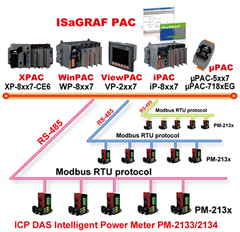
iPAC-8xx7 Series (iP-8417/8817/8447/8847) is a ISaGRAF SoftLogic PAC (Programmable Automation Controller) of
ICP DAS iPAC-8000 series. It is equipped with an 80186, 80 MHz CPU running a MiniOS7 operating system, various connectivity including Dual 10/100 Base-TX Ethernet Ports (for iP-8x47), one RS-232/485 port, one RS-485 port and two RS-232 ports, and 4/8 slots for high performance Parallel-type I/O modules (High profile I-8K series) and high performance Serial-type I/O modules (Hot-Swap High Profile I-87K series), etc. Compared with I-8xx7, iPAC-8xx7 series is 2 ~ 4 times faster! |
|
|
|
| |
|
|
| |
|
|
|
|
|
| |
 MiniOS7 Embedded Operating System (DOS-like) MiniOS7 Embedded Operating System (DOS-like) |
| ISaGRAF Ver.3 SoftLogic Inside |
| Support IEC 61131-3 Standard |
| Accepts max. 64 KB ISaGRAF code size |
| |
|
|
|
| |
|
|
| |
|
|
|
|
|
| |
| 80186 CPU (16-bit & 80 MHz) |
Support I/O Module Hot Swap |
| Dual Battery Backup SRAM (512 KB) |
Dual 10/100M Ethernet Ports (for iP-8x47) |
| 64-bit Hardware Serial Number for Protection |
4 Serial Ports (RS-232/485) |
| 4/8 I/O Expansion Slots (support High Profile I/O Modules) |
Redundant Power Inputs |
| |
|
|
|
| |
|
|
|
|
|
| |
|
|
| |
|
|
|
|
|
| |
|
|
| |
|
|
|
|
|
| |
|
|
| |
|
|
|
|
|
| |
| Models |
iP-8417 |
iP-8817 |
iP-8447 |
iP-8847 |
| System Software |
| OS |
MiniOS7 (DOS-like embedded operating system) |
| Development Software |
| ISaGRAF Software |
ISaGRAF Ver. 3 |
IEC 61131-3 standard |
| Languages |
LD, ST, FBD, SFC, IL & FC |
| Max. Code Size |
64 KB |
| Scan Time |
2 ~ 25 ms for normal program
10 ~ 125 ms (or more) for complex or large program |
| CPU Module |
| CPU |
80186, 80 MHz |
| SRAM |
512 KB |
768 KB |
| Flash |
512 KB; with Write Protect Switch |
| microSD Expansion |
Yes (but ISaGRAF doesn't support) |
| Dual Battery Backup SRAM |
512 KB; data valid up to 5 years (for retain variables) |
| EEPROM |
16 KB |
| NVRAM |
31 bytes (battery backup, data valid up to 5 years) |
| RTC (Real Time Clock) |
Provide second, minute, hour, date, day of week, month, year |
| 64-bit Hardware Serial Number |
Yes, for Software Copy Protection |
| Watchdog Timers |
Yes (0.8 second) |
| DIP Switch |
Yes (8 bits) |
| Communication Ports |
| Ethernet |
- |
RJ-45 x 2, 10/100 Base-TX
(Auto-negotiating, Auto MDI/MDI-X,
LED indicators) |
| COM 0 |
Internal communication with the high profile I-87K series modules in slots |
| COM 1 |
RS-232 (to update firmware) (RxD, TxD and GND); non-isolated |
| COM 2 |
RS-485 (Data+, Data-) with internal self-tuner ASIC; 3000 VDC isolated |
| COM 3 |
RS-232/RS-485 (RxD, TxD, CTS, RTS and GND for RS-232, Data+ and Data- for RS-485); non-isolated |
| COM 4 |
RS-232 (RxD, TxD, CTS, RTS, DSR, DTR, CD, RI and GND); non-isolated |
| SMMI |
| LED Display |
Yes, 5-Digit |
| Programmable LED Indicators |
3 |
| Push Buttons |
4 |
| Buzzer |
- |
- |
Yes |
| I/O Expansion Slots |
| Slot Number |
4 |
8 |
4 |
8 |
| Note: For High Profile I-8K and I-87K Modules Only |
| Data Bus |
8/16 bits |
| Address Bus Range |
2 K for each slot |
| Mechanical |
| Dimensions (W x L x H) |
231 mm x 132 mm x 111 mm: iP-8417, iP-8447
355 mm x 132 mm x 111 mm: iP-8817, iP-8847 |
| Installation |
DIN-Rail or Wall Mounting |
| Environmental |
| Operating Temperature |
-25 ~ +75°C |
| Storage Temperature |
-30 ~ +80°C |
| Ambient Relative Humidity |
10 ~ 90% RH (non-condensing) |
| Power |
| Input Range |
+10 ~ +30 VDC |
| Isolation |
1 kV |
| Redundant Power Inputs |
Yes, with one power relay (1 A @ 24 VDC) for alarm |
| Capacity |
30 W |
30 W |
30 W |
30 W |
| Consumption |
6.7 W |
7.2 W |
6.7 W |
7.2 W |
| Protocols (some protocols need optional devices) |
| NET ID |
8 bits DIP switch to assign NET ID as 1 ~ 255 |
| Modbus RTU/ASCII Master |
Max. 2 COM Ports, COM1 ~ COM5 can support Modbus RTU Master or ASCII Master protocol to connect to other Modbus Slave devices. Max. Modbus_xxx Function Block amount for 2 ports: 128. (*) |
| Modbus RTU Slave |
Max. 2 COM Ports, COM1 and one of (COM2, COM3) can support Modbus RTU Slave protocol for connecting ISaGRAF, PC/HMI/OPC Server & MMI panels. |
| Modbus TCP/IP Slave |
2 Ethernet ports support Modbus TCP/IP Slave Protocol for connecting ISaGRAF & PC/HMI. (Max. 6 connections) (for iP-8x47) |
| User-Defined Protocol |
COM1 ~ COM20 by serial communication function blocks (*) |
| Remote I/O |
One of COM2 or COM3 or COM4 supports I-7000 I/O modules & (I-87Kn or RU-87Pn + I-87K High Profile I/O boards) as Remote I/O. Max. 64 Remote I/O module for one PAC |
| Fbus |
Built-in COM3 Port to exchange data between ICP DAS’s ISaGRAF PACs. |
| Ebus |
To exchange data between ICP DAS’s ISaGRAF Ethernet PACs via Ethernet port.
(The LAN2: upper port ONLY) (for iP-8x47) |
| SMS: Short Message Service |
One of COM4/5 can link to a GSM Modem to support SMS. User can request data/control the controller by cellular phone. (*)
The controller can also send data & alarms to user’s cellular phone.
Optional GSM/GPRS modem: GTM-201-RS232 (850/900/1800/1900 GSM/GPRS External Modem) or the GSM/GPRS Modem on the website: http://www.icpdas.com/products/GSM_GPRS/wireless/GSM_GPRS_modem.htm |
| Modem Link |
COM4 can connect a general Modem. Supports PC to remotely download & monitor the controller. |
| MMICON/LCD |
One of COM3 or COM4 supports ICP DAS’s MMICON. The MMICON is featured with a 240 x 64 dot LCD and a 4 x 4 Keyboard.
User can use it to display picture, string, integer, float, and input a character, string, integer and float. |
| Redundant Bus7000 |
Two ISaGRAF PACs can link to remote I-7000 & I-87K High profile I/O modules at the same time.
Only one controller is active to control these Remote I/Os. If one is dead, the other one will take over the control of Remote I/Os. |
| CAN/CANopen |
COM1, 3, 4 or COM5 ~ COM12 (*) can connect one I-7530 (converter: RS-232 to CAN) to support CAN/CANopen devices and sensors. One iP-8xx7 supports max. 3 RS-232 ports to connect max. 3 I-7530. (FAQ-086) |
| FRnet I/O |
Support max. 4 I-8172W FRnet Master cards to connect FRnet I/O modules (Max. 1024-ch. DI + 1024-ch. DO) |
| Send Email |
Actively or passively sending Email via Ethernet port through internet. Max.10 receivers for each sending and can send Email with an attached file.
(Max. file size is about 488 KB) (for iP-8x47) |
| FTP Client |
Support FTP client to upload files in the PAC to a remote FTP server on PC. (FAQ-151) |
| Optional I/O Functions (Refer to ISaGRAF PAC I/O Selection Guide for I/O Module list) |
| PWM Output |
High Speed PWM Module |
I-8088W, 8-ch PWM outputs, software support 1 Hz ~ 100 kHz (non-continuous), duty: 0.1 ~ 99.9% |
| DO Module as PWM |
8-ch max. for one controller. 500 Hz max. For Off=1 & On=1 ms Output Square Curve: Off: 1 ~ 32767 ms, On: 1 ~ 32767 ms.
Optional DO Boards: I-8037W, 8041W, 8041AW, 8042W, 8050W, 8054W, 8055W, 8056W, 8057W, 8060W, 8063W, 8064W, 8068W, 8069W. (Relay Output boards cannot generate fast square wave) |
Counters,
Encoder,
Frequency |
Parallel DI Counter |
8-ch. max. for 1 controller. Counter Val: 32-bit.; 500 Hz max.
Min. ON & OFF width must >1 ms
Optional DI boards: I-8040W, 8040PW, 8042W, 8046W, 8050W, 8051W, 8052W, 8053W, 8053PW, 8054W, 8055W, 8058W, 8063W. |
Serial DI
Counter |
Counter input: 100 Hz max. Counter value: 0 ~ 65535 (16-bit)
Optional serial I-87K DI boards: I-87040W, 87046W, 87051W, 87052W, 87053W, 87053W-A5, 87054W, 87055W, 87058W, 87059W, 87063W. |
Remote DI
Counter |
All remote I-7000/I-87K DI modules support counters. 100 Hz max. value: 0 ~ 65535 |
| High Speed Counter |
I-87082W: 100 kHz max. 32-bit;
I-8084W: 250 kHz max. 32-bit |
| Encoder |
I-8093W: 3-axis Encoder Module, max. 1M Hz for quadrant input mode, max. 4M Hz for
pulse/direction and cw/ccw input mode. (FAQ-112)
I-8084W: 250 kHz max. , 4-ch encoder, can be Dir/Pulse, or Up/Down or A/B phase
(Quad. mode); Not support Encoder Z-index. (FAQ-100) |
| Frequency |
I-87082W: 2-ch, 1 Hz ~ 100 kHz;
I-87088W: 8-ch, 1 Hz ~ 100 kHz;
I-8084W: 8-ch, 1 Hz ~ 250 kHz; |
| Motion |
Motion Control |
Can integrate with one I-8091W (2-axis) or two I-8091W (4-axis) to do motion control. Ethernet communication is also available when doing motion control. |
* Note: COM5 ~ COM20 are resided at the expansion boards if they are plugged on slot 0 ~ 7 of iP-8xx7.
* ISaGRAF FAQ: http://www.icpdas.com/faq/isagraf.htm
* Recommend to use NS-205/NS-208 Industrial Ethernet Switch. |
|
|
| |
|
|
|
|
|
| |
|
|
| |
|
|
|
|
|
| |
| iP-8417 CR |
4 slots Faster CPU (80 MHz) ISaGRAF PAC (RoHS)
80186, 80MHz |
| iP-8817 CR |
8 slots Faster CPU (80 MHz) ISaGRAF PAC (RoHS)
80186, 80MHz |
| iP-8447 CR |
4 slots Faster CPU (80 MHz) Dual Ethernet ISaGRAF PAC (RoHS)
80186, 80MHz, 10/100 Mbps |
| iP-8847 CR |
8 slots Faster CPU (80 MHz) Dual Ethernet ISaGRAF PAC (RoHS)
80186, 80MHz, 10/100 Mbps |
|
|
| |
|
|
| |
|
|
|
|
|
| |
|
|
| |
Click here to see more optional accessories (Software & Hardware) |
|
| |
|
|
| |
|
|
|
|
|
| |
|
|
| |
Click here to see more ISaGRAF PAC |
|
| |
|
|
| |
|
|
|
|
|
| |
|
|
| |
|
|
|
|