| |
|
|
| |
|
|
| |
DIO-96 / DIO-144
96-channel OPTO-22 DIO Board / 144-channel OPTO-22 DIO Board |
|
|
|
|
|
|
|
| |
|
|
| |
|
|
| |
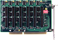
The DIO-144/96 provides 144/96 TTL digital I/O lines. The DIO-144/96 emulates 8255 mode 0 and has an increased output current of 15 mA (source) and 64 mA (sink) , allowing it to control LED, relay, etc. The DIO-144/96 consists of eighteen 8 bit bi-directional ports and 2 input lines for interrupt enable and interrupt. The 8 bit ports are named port A(PA),port B(PB) and port C(PC). The port C can be split into two four bit. All port are configured as inputs upon power-up or reset. The DIO-144/96 uses 4 consecutive I/O locations in I/O addressing space. The base address is selectable from 200 to 3FF hex. The interrupt signal can be connected to any of the interrupt levels 2 through 15 . |
|
|
| |
back |
|
|
|
|
| |
|
|
| |
|
|
| |
- Double side SMT , short card, power saving
- DIO-144 : 144 digital I/O lines
DIO-96 : 96 digital I/O lines
- Emulate 8255 mode 0 (Basic Input / Output mode)
- Buffer output for higher driving capability than 8255
- Register compatible to 722 series
- Programmable interrupt handling
- DIO-144 : Six 50-pin Header
DIO-96 : Four 50-pin Header
- Output status readback
|
|
|
| |
back |
|
|
|
|
| |
|
|
| |
|
|
| |
- Factory automation
- Product test
- Test automation
|
- Digital I/O control
- Alarm monitoring
- 4-channel SSR Output Daughter Board
|
|
|
| |
back |
|
|
|
|
| |
|
|
| |
|
|
| |
- DOS sample program(with source codes)
- DLL and OCX SDK for Windows 98/NT/2000
- DLL and OCX SDK for 32-bit Windows XP/2003/Vista/7
- VB/VC/Delphi/BCB sample programs with source codes are included
- LabVIEW toolkit for Windows
- Driver for Linux and DasyLab
|
|
|
| |
back |
|
|
|
|
| |
|
|
| |
|
|
| |
| Model Name |
DIO-96 |
DIO-144 |
| Digital Input |
| Channels |
96 (OPTO-22 compatible) |
144 (OPTO-22 compatible) |
| Compatibility |
5 V/TTL |
| Input Voltage |
Logic 0: 0.8 V max.
Logic 1: 2.0 V min. |
| Response Speed |
1.0 MHz (Typical) |
| Digital Output |
| Channels |
96 (OPTO-22 compatible) |
144 (OPTO-22 compatible) |
| Compatibility |
5 V/TTL |
| Output Voltage |
Logic 0: 0.4 V max.
Logic 1: 2.4 V min. |
| Output Capability |
Sink: 0.8 mA @ 0.8 V
Source: -2.4 mA @ 2.0 V |
| Response Speed |
1.0 MHz (Typical) |
| General |
| Bus Type |
ISA |
| I/O Connector |
50-pin box header x 4 |
50-pin box header x 6 |
| Dimensions (L x W x D) |
182 mm x 120 mm x 22 mm |
| Power Consumption |
800 mA @ +5 V |
700 mA @ +5 V |
| Operating Temperature |
0 ~ 60 ¢XC |
| Storage Temperature |
-20 ~ 70 ¢XC |
| Humidity |
5 ~ 85% RH, non-condensing |
|
|
|
|
|
| |
back |
|
|
|
|
| |
|
|
| |
|
|
| |
| DIO-96 |
96-channel Digital I/O Board |
| DIO-96 CR |
96-channel Digital I/O Board (RoHS) |
| DIO-144 |
144-channel Digital I/O Board |
|
|
|
|
| |
back |
|
|
|
|
| |
|
|
| |
|
|
| |
| CA-5002 |
50-pin flat cable 20 cm |
| CA-5015 |
50-pin flat cable 1.5 M |
| DB-24P |
24-channel Photo Couple Isolated Digital Input Daughter Board |
| DB-24R |
24-channel Relay Output Daughter Board |
| DB-24C |
24-channel Open Collector Output Daughter Board |
| DB-16P8R |
16-channel Isolated Digital Input And 8-channel Relay Output Daughter Board |
| DB-24POR |
24-channel Photo Mos Relay Output Daughter Board |
| DB-24PR |
24-channel Power Relay Output Daughter Board |
|
|
| |
|
|
|
|
|
| |
back |
|
| |
|
|
| |
|
|
| |
|
|
| |
|
|
|
|
|
| |
back |
|
| |
|
|