CAN Bus Isolated Repeater

Features
- Compatible with CAN specification 2.0A and 2.0B
- Fully compatible with the ISO 11898-2 standard
- Maximum communication baud : 800Kbps
- 2500 VRMS photo coupler isolation on the CAN side
- 3KV galvanic isolation among the power supply and 2 CAN ports
- Jumper for 120Ω terminal resistor of the CAN bus
- Two CAN channels
- Auto-baud detection
- up to 100 nodes on each CAN port
- Removable terminal block
- Mount easily on DIN-rail
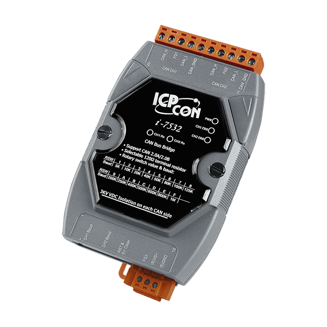
Introduction
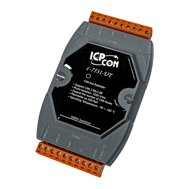
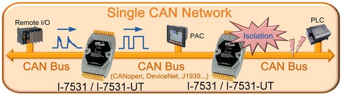
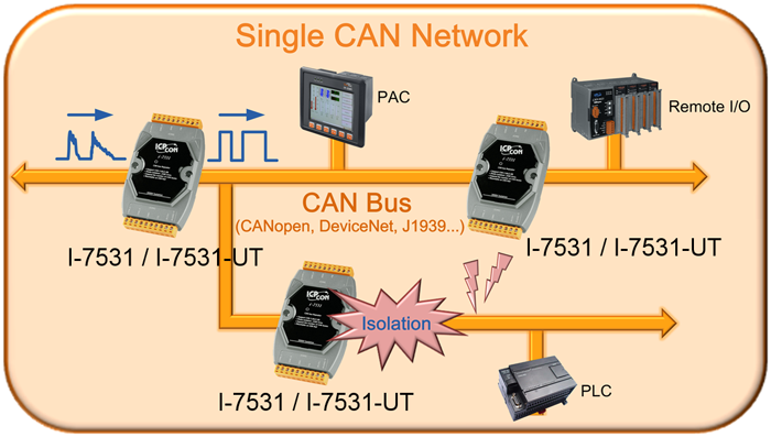
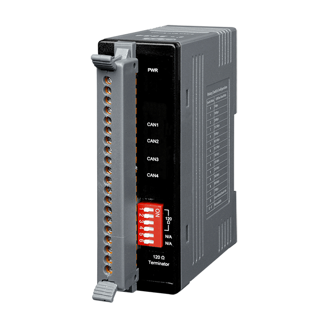
The I-7531-UT is an isolated CAN repeater that can be used to establish a physical coupling of two segments of a CAN bus system. This module is designed to isolate the noise and disturbance between the two CAN ports of the I-7531-UT. When the CAN signal is decayed because of the rough bus cable or noise, the I-7531-UT can recover the shape of the CAN signals to the original ones. Tree topologies can be implemented as well as long drop lines using the I-7531-UT. In order to use the I-7531-UT easily, the module can automatically adjust the baud rate by itself to match the CAN network. Users just connect the I-7531-UT with the CAN buses, check the terminal resistor and power it on, subsequently the I-7531-UT enable to work normally. For detail information , please refer to the user manual of I-7531-UT.
Applications
• Control System
• Building Automation
• Factory Automation
• Distributed data acquisition
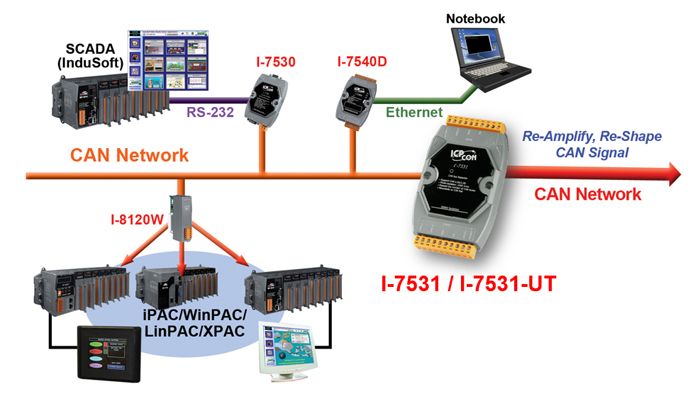
Application Architecture
Ordering Information
| PRODUCT SERIES | DESCRIPTION | QNT. | INQUIRY |
|---|---|---|---|
This combination include other products.
Similar Products
| Fiber | |
|---|---|
| Propagation Delay | 200 ns |
| CAN | |
|---|---|
| Ports | 2 |
| Specification | ISO-11898-2, CAN 2.0A and CAN 2.0B |
| Baud Rate | 5 k ~ 800 k bps |
| Isolation | 3000 VDC for DC-to-DC, 2500 Vrms for photo-couple |
| Terminal Resistor | Jumper for 120 Ω terminal resistor |
| Time Delay | 200ns |
| Power | |
|---|---|
| Input Range | +10 VDC ~ +30 VDC |
| Consumption | 2 W |
| Mechanical | |
|---|---|
| Casing | Plastic |
| Dimensions (mm) | 72 x 118 x 33 (W x L x H) |
| Installation | DIN-Rail |
| Environment | |
|---|---|
| Operating Temperature | -40 ~ +85 °C |
| Storage Temperature | -45 ~ +90 °C |
| Humidity | 10 ~ 90% RH, Non-condensing |
The relationship between ideal total bus length and baud are displayed below.
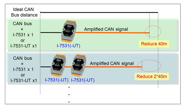
Note:When users apply one I-7531-UT into a CAN network, the ideal CAN communication distance will be reduced 40 meters. For example, if the CAN network is under 500K bps baud rate and one I-7531-UT is applied in the network, the ideal total bus length becomes 100-40*1=60 meters. If using two I-7531-UTs in this network, the communication distance is 100-40*2=20 meters.
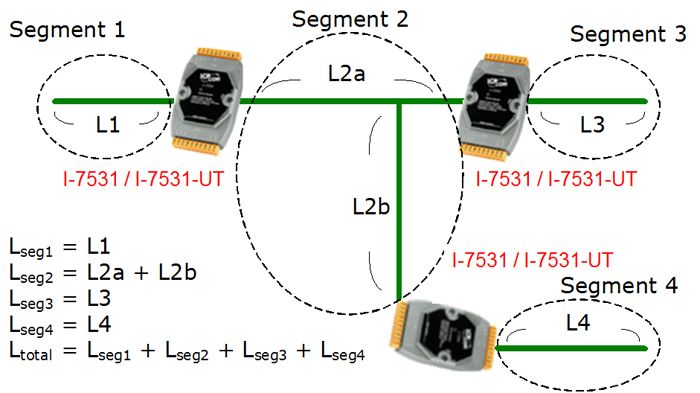
After deciding the number of I-7531-UT and calculating the corresponding ideal bus length, users can use the following table to know the maximum node number in each segment and the maximum segment length when using different type of wire.
Note:The definition of segment and the relationship between segment length (Lseg1, Lseg2 …) and ideal total bus length (Ltotal) are shown in the following figure.
| Baud [bit/sec] | Ideal Bus Length without I-7531-UT [m] |
|---|---|
| 800K | 50 |
| 500K | 100 |
| 250K | 250 |
| 125K | 500 |
| 50K | 1000 |
| 20K | 2500 |
| 10K | 5000 |
Note:When users apply one I-7531-UT into a CAN network, the ideal CAN communication distance will be reduced 40 meters. For example, if the CAN network is under 500K bps baud rate and one I-7531-UT is applied in the network, the ideal total bus length becomes 100-40*1=60 meters. If using two I-7531-UTs in this network, the communication distance is 100-40*2=20 meters.
After deciding the number of I-7531-UT and calculating the corresponding ideal bus length, users can use the following table to know the maximum node number in each segment and the maximum segment length when using different type of wire.
| Wire Cross- Section [mm2] |
The maximum segment length [m] under the case of specific node number in this segment |
||
|---|---|---|---|
| 32 Nodes | 64 Nodes | 100 Nodes | |
| ~0.25 (AWG23) | <200 m | <170 m | <150 m |
| ~0.5 (AWG20) | <360 m | <310 m | <270 m |
| ~0.8 (AWG18) | <550 m | <470 m | <410 m |
| ~1.3 (AWG16) | <900 m | <780 m | <670 m |