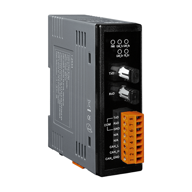
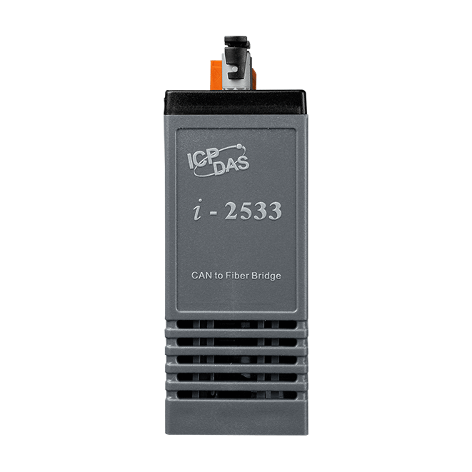
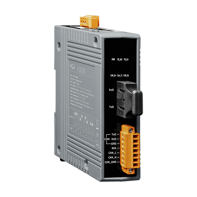
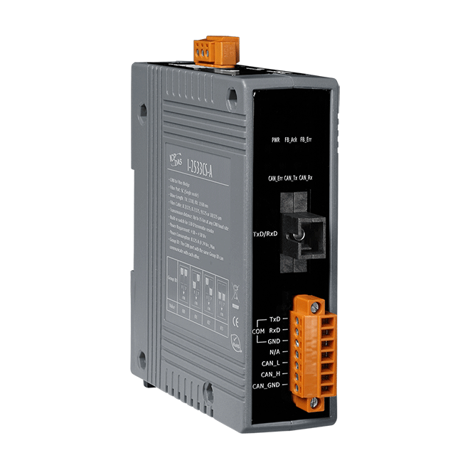
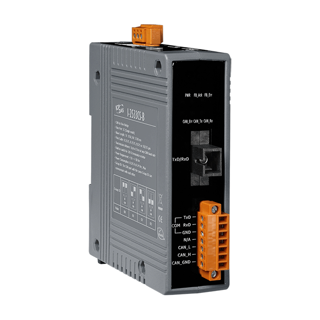
I-2533
CAN to Multi-mode Fiber Bridge
Features
- Support both CAN 2.0A and CAN 2.0B specification
- Fully compatible with the ISO 11898-2 standard
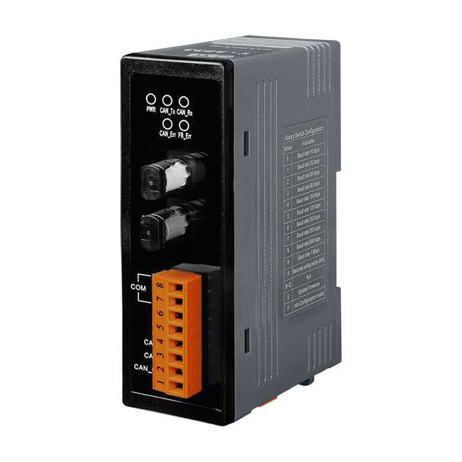
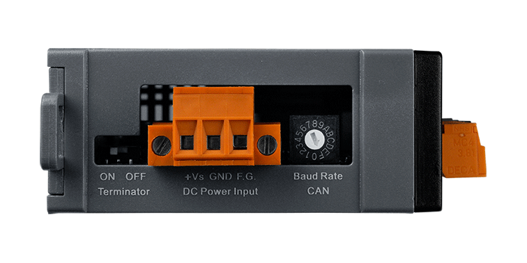
- Rotary switch for CAN baud rate configuration
- Up to 100 CAN nodes on the CAN channel (*Note)
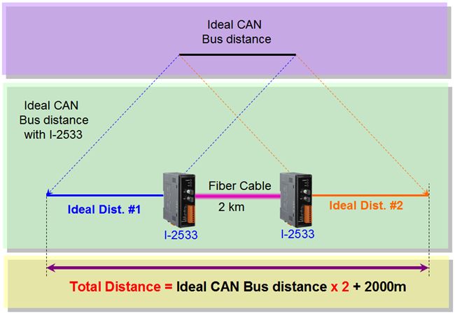
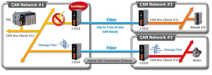
- Transmission distance up to 2 km at any CAN baud rate
- Provides the 512-record CAN Tx buffer and 512-record CAN Rx buffer
- Allow user-defined baud rate
- Software utility tool for message filter configuration
- Fiber Port: ST (Multi-mode)
- Broken line detection for fiber cable
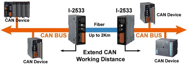
Introduction
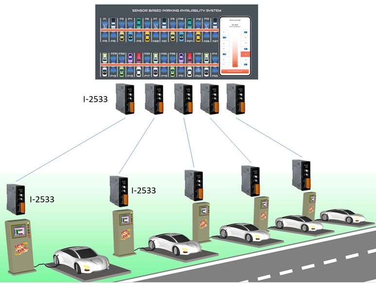
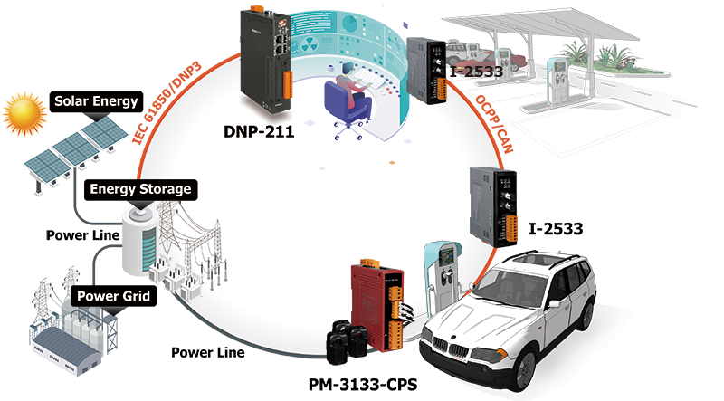
The I-2533 is an intelligent CAN bridge that can be used to establish the connection between two CAN bus systems via fiber optic cable. Similar to the I-2532, the I-2533 can also apply in various CAN-based protocols to convert CAN bus signals to optical signals and reshape the CAN signals. The difference between the I-2532 and I-2533 is the CAN configuration functions and the distance limitation of CAN communication. The I-2533 offers the functions to configure the CAN baud rate and CAN message filters. These are useful when using the I-2533 to link two CAN networks which may have different baud rates. By using the I-2533, the transmission distance limitation of the CAN bus system will not be reduced because of the CAN baud rate, which means that the total network length can be extended. This feature means that users can develop the applications more powerful and flexible with the I-2533.
Applications
- Control System
- Building Automation
- Factory Automation
- Distributed data acquisition
- EV(Electric Vehicle) charging station
Ordering Information
| PRODUCT SERIES | DESCRIPTION | QNT. | INQUIRY |
|---|---|---|---|
This combination include other products.
Similar Products
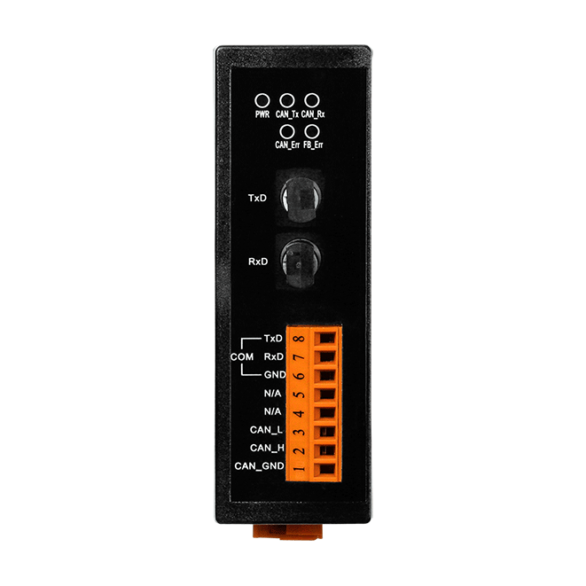
| LED Indicators | |
|---|---|
| Status | 1 x Power 3 x CAN status 1 x Fiber |
| COM Ports | |
|---|---|
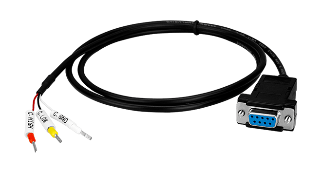
| Ports | 1 x RS-232 (Utility Port) |
| Fiber | |
|---|---|
| Ports | Multi Mode; ST connector x 1 |
| Fiber Cable | 50/125, 62.5/125 or 100/140 μm (62.5/125μm is recommended) |
| Wavelength | 850 nm |
| Transmission Distance | 2 km max (62.5 / 125 μm recommended) |
| Propagation Delay | 250 us (*Note1) |
| CAN | |
|---|---|
| Ports | 1 |
| Specification | ISO-11898-2, CAN 2.0A and CAN 2.0B |
| Baud Rate | 10 k ~ 1 M bps |
| Isolation | 3000 VDC for DC-to-DC, 2500 Vrms for photo-couple |
| Terminal Resistor | Switch for 120Ω terminal resistor |
| Filter | Yes |
| Power | |
|---|---|
| Input Range | +10 VDC ~ +30 VDC |
| Consumption | 3 W |
| Mechanical | |
|---|---|
| Casing | Plastic |
| Dimensions (mm) | 32.3 x 77.5 x 99.0 (W x L x H) |
| Installation | DIN-Rail |
| Environment | |
|---|---|
| Operating Temperature | -25 ~ +75 °C |
| Storage Temperature | -30 ~ +80 °C |
| Humidity | 10 ~ 90% RH, Non-condensing |
Specification Memo
Note1:
The propagation delay depends on the CAN Bus baud rate and the CAN message format. This value has been tested using a CAN baud rate of 1 Mbps, the CAN ID 0x12345678 and 8 bytes of data with a value of 0xFF.
The propagation delay depends on the CAN Bus baud rate and the CAN message format. This value has been tested using a CAN baud rate of 1 Mbps, the CAN ID 0x12345678 and 8 bytes of data with a value of 0xFF.

| Baud [bit/sec] | Ideal Fiber Length [m] |
|---|---|
| 1M | 2000 |
| 800K | 2000 |
| 500K | 2000 |
| 250K | 2000 |
| 125K | 2000 |
| 50K | 2000 |
| 20K | 2000 |
| 10K | 2000 |