|
|
 |
|
|
PISO-DNM100-D / PISO-DNM100-T
PISO-DNM100U-D / PISO-DNM100U-T
1 Port Intelligent DeviceNet Master Communication Board with DeviceNet Firmware Inside |
|
|
| |
| |
|
|
|
|
| |
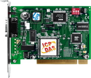
PISO-DNM100-D
|
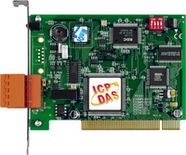
PISO-DNM100-T
|
|
| |
|
|
|
| |
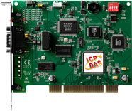
PISO-DNM100U-D
~New~ |
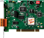
PISO-DNM100U-T
~New~ |
|
|
|
|
| |
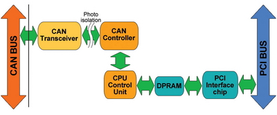
PISO-DNM100 can represent an economic solution of DeviceNet application and be a DeviceNet master device on the DeviceNet network. It is a "Predefined Master-Slave connection Set". PISO-DNM100 supports Group 2 only Server and UCMM functions to communication with slave devices. It has an independent CAN bus communication port and has the ability to cover a wide range of DeviceNet applications. |
|
| |
Besides, PISO-DNM100 uses the new CAN controller Phillips SJA1000T and transceiver 82C250/251, which provide bus arbitration, error detection with auto correction and re-transmission function.It can be installed on almost any windows-based system, for example Win98/Win2000/WinXP. It is popularly applied in the industrial automation, building automation, vehicle, marine, and embedded control network. In order to expand the DeviceNet functions of ICPDAS products, PISO-DNM100 is developed for this purpose. |
.jpg) |
|
|
|
|
| |
|
|
| |
|
|
| |
• Industrial Machinery • Building Automation • Medical • Maritime • Restaurant Appliances
• Laboratory Equipment & Research
 |
| |
|
|
|
| |
|
| |
|
| |
DeviceNet Version: Volume I & II, Release 2.0
-
Programmable master MAC ID and baud rate
-
Baud Rate: 125 kbps, 250 kbps, 500 kbps
-
Support Group 2 and UCMM connection
-
I/O Operating Modes: Poll, Bit-Strobe, Change of State / Cyclic
-
I/O Length: max 512 input bytes and 512 output bytes pre slave
-
Slave Node : 63 nodes max
-
Support auto-search slave device function
-
Support on-line adding and removing devices
-
Support auto-detect Group 2 and UCMM device
-
Auto-reconnect when the connection is broken
-
LED: Status,ERR
|
| |
|
|
|
| |
|
|
| |
|
|
| |
-
Programmable Master MAC ID
-
Programmable transfer-rate 125 kbps, 250 kbps, 500 kbps
-
Each port support maximum nodes up to 64
-
Support Group 2 Only Server functions
-
Support UCMM functions
-
Predefined Master-Slave Connection Set
-
The maximum Fragment number is (Input/Output) up to 64
-
Support I/O Operation Mode: Poll, Bit-Strobe and Change Of State/Cyclic
-
Support Auto-Scan slave device function
-
Support on-line adding and removing devices
-
Support boot-up auto communicating with slave devices
-
Support Auto-Reconnect when the connection is broken
We have communicated with the following DeviceNet slaves
-
Allen-Bradley PowerFlex series DeviceNet Inverters
-
BECKHOFF CX1500-B520 series DeviceNet I/O modules
- BECKHOFF BK5250 series DeviceNet I/O modules
- MKS 683 series DeviceNet exhaust throttles
- MKS MFC (Mass Flow Controller) series DeviceNet devices
- MKS DELTA II FRC (Flow Ratio Controller) series DeviceNet devices
- MKS DC Power Generator (OPT- xxx) series DeviceNet devices
- OMRON DRT1-ID/ODxx series DeviceNet I/O modules
- OMRON DRT2-MDxx series DeviceNet I/O modules
- COSMOS PS-7 series DeviceNet gas detectors
- CELERITY UNIT IFC-125 series DeviceNet devices
|
| |
|
| |
|
| |
|
|
|
|
|
| |
|
|
| |
|
|
| |
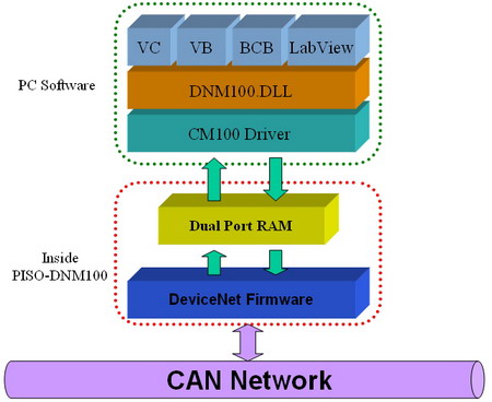
There exist two memory areas, “Input Area” and “Output Area”. The input data of all DeviceNet slaves would be stored in the “Input Area” by DeviceNet master scan engine. Oppositely, the output data of those DeviceNet slaves would be in the “Output Area”. Please refer to the following figure.
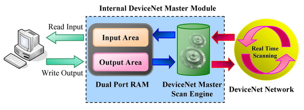
Users can read a bulk data from “Input Area” in the DeviceNet Master module, like PISO-DNM100U or I-8124W. This bulk data contains multiple devices’ input statuses. If one of the input status of the remote DeviceNet slave changes, the corresponding data located in the “Input Area” would change immediately. Oppositely, the “Output Area” contains multiple devices’ output data. Users may change the output value of a certain device by changing the corresponding data located in the “Output Area”. |
|
| |
|
|
|
|
|
| |
|
|
| |
|
|
| |
-
Development Toolkit for Windows NT4.0
-
Development Toolkit for Windows 98/ME
-
Development Toolkit for Windows 2000/XP/Vista
-
Development Toolkit for Windows 7 32-bit
|
|
| |
|
|
|
|
|
| |
|
|
| |
|
|
| |
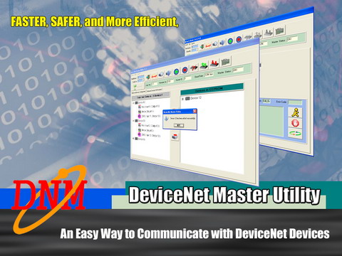
This utility supports to search all devices and specific devices in the network. These functions help the users to configure the connection of the slave devices. Anymore, the software also can diagnose the remote slave devices when building the DeviceNet network.
This software supports the users to configure the I/O connection of the devices by searching devices or manual setting. After configuring the I/O connection, the information would be saved into the EEPROM. The users can export the data from the EEPROM easily. Correspondingly, the users can import the data into the EEPROM.
The software utility can easily to access the I/O data of all the slave devices. The users can monitor the input data of the specific slave device and change the output data to the remote slave device with this utility.
|
|
| |
|
|
|
|
|
| |
|
|
| |
|
|
| |
| Item |
Description |

InduSoft Driver |
The IndoSoft is one of the famous and high performance SCADA. Nowaday, it supports the CAN, CANopen and DeviceNet driver for all the coresponding converter or master series products. [more...] |
|
|
| |
|
|
|
|
|
| |
|
|
| |
|
|
| |
|
|
| |
|
|
|
|
|
| |
|
|
| |
|
|
| |
Product Name |
PISO-DNM100 |
PISO-CAN-200/400
with DeviceNet Library |
Protocol decoder |
186 CPU |
PC CPU |
Time stamp |
186 Timer
(0.1 ms)
|
PC Timer
(about 1 ms) |
CPU Loading |
Light |
Heavy |
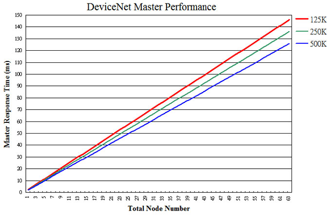
Performance |
High |
Normal |
Application |
Various and complex DeviceNet application |
General purpose DeviceNet application |
Hardware/Firmware Feature
Items |
DeviceNet Product |
PISO-DNM100 |
PISO-CAN-200/400
with DeviceNet Library |
On-board CPU |
Intel 80186, 80Mhz |
None |
DeviceNet Protocol Core |
In Firmware |
In PC driver |
Access node’s I/O |
Firmware |
PC driver |
Reconnect when breaking |
Support |
By User Programming |
Group 2 / Group 3 Checking |
Support |
By User Programming |
Search Slave Devices |
Support |
By User Programming |
Save Slave information |
EEPROM |
By User Programming |
Node No. |
Items |
DeviceNet Product |
PISO-DNM100 |
PISO-CAN-200/400 |
1 Nodes |
PC CPU loading |
1 % |
9 % |
2 Nodes |
PC CPU loading |
0 % |
27 % |
4 Nodes |
PC CPU loading |
0 % |
68 % |
8 Nodes |
PC CPU loading |
0 % |
100 % |
Test Environment: |
| |
Windows:Microsoft Windows XP Professional Version 2002 Service Pack 2
CPU:AMD Athlon(tm) 64 X2 Dual Core Processor 3800+ 2.00GHz
RAM:512 MB |
| |
|
|
|
| |
|
|
|
|
|
| |
|
|
| |
|
|
| |
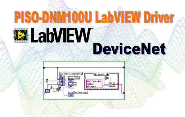
In order to develop complex DeviceNet applications, we provide a LabVIEW driver for this purpose. The PISO-DNM100(U) LabVIEW driver is the function reference to the DeviceNet master. We provide many useful VI functions in the LabVIEW environment. We also have the "DeviceNet Master Utility" to configure the DeviceNet hardware in your PC. The users not only operate easily and develop application rapidly, but also reduce the complexity of applications. The users can communicate with the remote DeviceNet devices in a few simple steps and need not to know about the detail of the DeviceNet protocol. It is the best tool to develop various distributed systems and other industrial applications software on DeviceNet network.
|
|
| |
|
|
|
|
|
| |
|
|
| |
|
|
| |
Model Name |
PISO-DNM100-D |
PISO-DNM100-T |
PISO-DNM100U-D |
PISO-DNM100U-T |
Bus Interface |
Type |
PCI bus, 5 V, 33 MHz, 32-bit, plug and play |
Universal PCI supports both 5 V and 3.3 V PCI bus |
Board No. |
By DIP switch |
CAN Interface |
Controller |
NXP SJA1000T with 16 MHz clock
Microprocessor inside with 80186 80MHz |
Transceiver |
NXP 82C250 |
Channel number |
1 |
Connector |
9-pin male D-Sub (CAN_GND, CAN_L, CAN_SHLD, CAN_H, N/A for others) |
5-pin screwed terminal block (CAN_L, CAN_SHLD, CAN_H, N/A for others) |
9-pin male D-Sub (CAN_GND, CAN_L, CAN_SHLD, CAN_H, N/A for others) |
5-pin screwed terminal block (CAN_L, CAN_SHLD, CAN_H, N/A for others) |
Baud Rate (bps) |
125 k, 250 k, 500 k |
Transmission Distance (m) |
Depend on baud rate (for example, max. 1000 m at 50 kbps ) |
Isolation |
3000 VDC for DC-to-DC, 2500 Vrms for photo-couple |
Terminator Resistor |
Jumper for 120 Ω terminator resistor |
Specification |
ISO-11898-2, CAN 2.0A and CAN 2.0B |
Protocol |
DeviceNet Volumn I ver2.0, Volumn II ver2.0 |
LED |
Round LED |
Green LED, Red LED |
Software |
Driver |
Windows 98/ME/NT/2K/XP |
Library |
VB 6.0, VC++ 6.0, BCB 6.0 |
Power |
Power Consumption |
300 mA @ 5 V |
Mechanism |
Dimensions |
138mm x 22mm x 92mm (W x L x H) |
138mm x 22mm x 105mm (W x L x H) |
Environment |
Operating Temp. |
0 ~ 60 ℃ |
Storage Temp. |
-20 ~ 70 ℃ |
Humidity |
5 ~ 85% RH, non-condensing |
|
|
| |
|
|
|
|
|
| |
|
|
| |
|
|
| |
PISO-DNM100-D |
DeviceNet firmware built-in and one standalone intelligence CAN communication port with D-Sub 9-pin connector for PCI bus system |
PISO-DNM100-T |
DeviceNet firmware built-in and One standalone intelligence CAN communication port with 5-pin screw terminal connector for PCI bus system |
PISO-DNM100U-D |
DeviceNet firmware built-in and one standalone intelligence CAN communication port with D-Sub 9-pin connector for universal PCI bus system |
PISO-DNM100-T |
DeviceNet firmware built-in and One standalone intelligence CAN communication port with 5-pin screw terminal connector for universal PCI bus system |
|
|
| |
|
|
|
|
|
| |
|
|
| |
|
|
| |
|
CAN bus Connector |
|
9-pin Female D-sub & 3-wire CAN bus cable (1M) |
|
7/14 channel Surge Protector |
|
EMI Ferrite Split/Snap-On Core
|
|
Field-Installation A-coded 5-pin Female
|
|
|
| |
|
|
| |
|
|
|
|