|
|
 |
|
| |
|
|
|
|
| |
|
I-7530A-MR
~ NEW ~
Modbus RTU to CAN Converter |
|
|
|
|
|
|
|
| |
|
|
| |
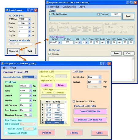
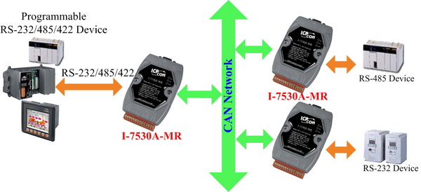
The I-7530A-MR is helpful for data exchanging between the RS-232/485/422 devices and the CAN devices. It supports three communication modes: “Normal”, “Modbus RTU”, “Pair-connection”.
In the Normal mode, the I-7530A-MR is designed to unleash the power of CAN bus via RS-232/485/422 communication method. It accurately converts ASCII format messages and CAN messages between RS-232/485/422 and CAN networks. This mode let you to communicate with CAN devices easily from any PC or programmable devices with RS-232/485/422 interface.
In Modbus RTU mode, it allows a Modbus RTU master to communicate with CAN devices on a CAN network. The following figure shows the application architecture of this mode.
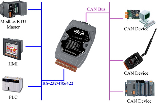
In pair-connection mode, this module provides the transparent communication between the RS-232/485/422 devices via CAN bus. The application architecture may be as follows.
|
|
|
|
|
| |
|
|
| |
|
|
| |
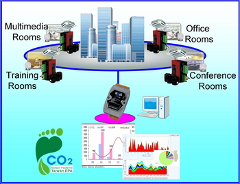
• Control System
•
Building Automation
• Factory Automation
• Distributed
data acquisition
|
|
|
| |
|
|
|
|
|
| |
|
|
| |
|
|
| |
-
-
Fully compatible with ISO 11898-2 standard
-
Programmable CAN bus baud rate from 10 kbps to 1 Mbps or user-defined baud rate
-
Support CAN bus acceptance filter configuration
-
Support firmware update via RS-232
-
Provide utility tool for module setting and CAN bus communication testing
-
Built-in jumper to select 120Ω terminator resistor
-
CAN buffer: 128 data frames ; UART buffer: 256 bytes
-
Power, data flow and error indicator for CAN and UART status
-
-
Convert CAN message to specific ASCII command string (Normal mode)
-
Convert specific ASCII command string to CAN message (Normal mode)
-
Provide the transparent communication between the RS-232/485/422 devices via CAN bus (Pair-connection mode)
-
Support function code 0x03/0x04/0x10 of Modbus RTU command for reading and writing CAN message (Modbus RTU mode)
|
|
| |
|
|
|
|
|
| |
|
|
| |
|
|
| |
-
CAN bus Baud Rate configuration
-
CAN acceptance filter configuration
-
CAN 2.0A or 2.0B specific selection
-
RS-232/485/422 baud rate and data format configuration
-
RS-232/485/422 communication with checksum function selection
-
Communication mode setting
-
Easily transmit/receive CAN messages
|
|
|
| |
|
|
|
|
|
| |
|
|
| |
|
|
| |
| Item |
Description |
CAN bus Power Meter |
This is the software solution for the CAN bus power meter(PM-213x-CAN). It is convenient to collect the distributed power information via CAN bus. [more...] |
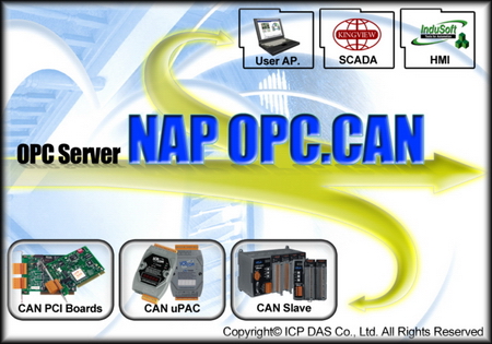
CAN OPC Server |
This is the OPC server for all the SCADA like LabVIEW, iFix, DASYLab and etc. By using the OPC server, the users be able to control any CAN devices via the famous SCADA. [more...] |
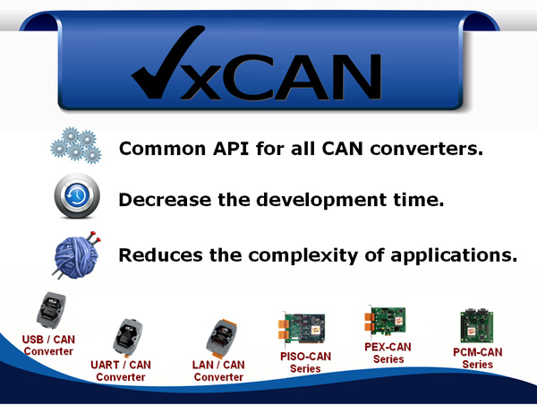
VxCAN Driver |
The VxCAN driver is the virtual CAN driver for all CAN converters and CAN master products. Even using different products, the users could use the same APIs to develop any CAN applications. [more...] |

InduSoft Driver |
The IndoSoft is one of the famous and high performance SCADA. Nowaday, it supports the CAN, CANopen and DeviceNet driver for all the coresponding converter or master series products. [more...] |
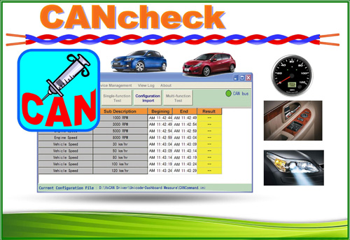
CANcheck |
This is the software for diagnosing and testing the user's CAN devices. The graphical interface is ready-made and easy to operate. [more...] |

CAN Test Tool |
The CAN test tool can help users to test the CAN communication of CAN series of ICP DAS by the simple steps. This tool is based on VxCAN driver and supports most of all CAN products of ICP DAS [more...] |
|
|
| |
|
|
|
|
|
| |
|
|
| |
|
|
| |
RS-232/422 full-duplex communication mode |
CAN setting |
RS-232/422 setting |
RS-232/422 command length |
The max frames/sec |
2.0B, 1Mbps |
115200,n,8,1 |
27 Bytes |
370 |
2.0B, 1Mbps |
230400,n,8,1 |
27 Bytes |
666 |
2.0B, 1Mbps |
460800,n,8,1 |
27 Bytes |
1250 |
|
|
| |
|
|
|
|
|
| |
|
|
| |
|
|
| |
Hardware |
EEPROM |
16 KB (for system information), 10,000,000 erase/write cycles
|
CAN Interface |
Transceiver |
NXP 82C250 |
Connector |
9-pin male D-Sub (CAN_L, CAN_H, N/A for others) |
Channels |
1 |
Baud Rate (bps) |
10 k, 20 k, 50 k, 100 k, 125 k, 250 k, 500 k, 800 k and 1 M (allow user-defined baud rate) |
Protection |
3000VDC power protection and 3750Vrms photo-couple isolation on CAN side |
Terminator Resistor |
Selectable 120Ω terminator resistor by jumper |
Support Protocol |
ISO-11898-2, CAN 2.0A and CAN 2.0B |
Pin Assignment |
C.I.A. DS-102 (CAN_H=7, CAN_L=2) |
UART Interface |
COM |
RS-232/RS-485/RS-422 (can’t be used simultaneously) |
Connector |
14-pin terminal connector
RS-232 : TxD, RxD, GND
RS-422 : TxD+, TxD-, RxD+, RxD-
RS-485 : DATA+, DATA- |
Baud Rate (bps) |
300,600,1200, 2400, 4800, 9600, 19200, 38400, 57600, 115200, 230400 |
Protection |
3000VDC power protection and 2500Vrms photo-couple isolation on UART side |
LED |
Round LED |
PWR/CAN/UART |
Power |
Power supply |
+10 ~ +30 VDC |
Power Consumption |
1.5 W |
Dip Switch |
Init (Firmware Update, Module Configuration)/Normal (Firmware Operation) |
Mechanism |
Installation |
DIN-Rail |
Dimensions |
72mm x 118mm x 35mm (W x L x H) |
Environment |
Operating Temperature |
-25 ~ 75 ℃ |
Storage Temperature |
-30 ~ 80 ℃ |
Humidity |
10 ~ 90% RH, non-condensing |
|
|
| |
|
|
|
|
|
| |
|
|
| |
|
|
| |
I-7530A-MR CR
|
Modbus RTU to CAN converter (RoHS)
|
|
|
| |
|
|
|
|
|
| |
|
|
| |
|
|
| |
|
CAN bus Connector |
|
9-pin Female D-sub & 3-wire CAN bus cable (1M) |
|
7/14 channel Surge Protector |
|
EMI Ferrite Split/Snap-On Core
|
|
Field-Installation A-coded 5-pin Female
|
|
|
| |
|
|
| |
|
|
|
|