|
|
 |
|
|
I-7530 / I-7530T / I-7530FT 
RS-232 to CAN Converter |
|
|
|
|
|
|
| |
|
|
|
|
| |
I-7530 / |
I-7530T
~NEW~ |
I-7530-FT
|
|
|
|
|
|
|
| |
|
|
| |
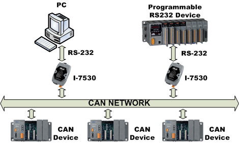
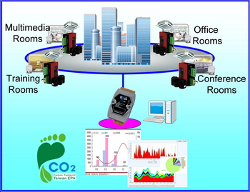
CAN (Controller Area Network) is a serial bus system especially suited to structure intelligent industry devices networks and build smart automatic control systems. The following figure shows the application architecture for I-7530/I-7530T/I-7530FT modules. The PC can be the CAN host, monitor or HMI to access/control the CAN device through the CAN network by the I-7530/I-7530T/I-7530FT Converters. The programmable RS-232 device (For example: I-8411/I-8431/I-8811/I-8831/W-8031/W-8331/W-8731 embedded controller) can use the serial port to connect to the CAN network via the I-7530/I-7530T/I-7530FT modules. In order to use the CAN network with traditional RS-232 devices, we provide a way to achieve this purpose. The I-7530/I-7530T/I-7530FT are designed to unleash the power of CAN bus via RS-232 communication method. It accurately converts messages between CAN and RS-232 networks. This module let you to communicate with CAN devices easily from any PC or devices with RS-232 interface.
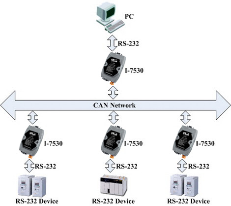
Moreover, we expand the functionalities of I-7530/I-7530T/I-7530FT for some special application. In pair connection mode, I-7530/I-7530T/I-7530FT can be used to connect PC with other RS-232 devices at the same time. The application architecture may be as follows.
3000V isolation on CAN side (for I-7530/I-7530T)
The CAN port of I-7530/I-7530T is an isolated with 3000V isolation. This isolation can protect the local RS-232 devices from the damage signal coming from CAN network.
Watchdog inside
The watchdog is a hardware reset circuit to monitor the operation status. When working in harsh or noisy environment, the I-7530/I-7530T/I-7530FT may shut down by the external signal. The circuit may let the I-7530/I-7530T/I-7530FT to work continuously and never halt.
Power and Error indicator display
There are two indicators on the I-7530/I-7530T/I-7530FT.The power indicator can help user to check whether the I-7530/I-7530T/I-7530FT is standby or transmitting/receiving messages. The Error indicator will be turned on when some errors occur on the I-7530/I-7530T/I-7530FT.
|
|
|
|
|
| |
 |
|
| |
|
|
| |
• Control System•
Building Automation• Factory Automation• Distributed
data acquisition
 |
|
| |
|
|
|
|
|
| |
|
|
| |
|
|
| |
-
Compatible with CAN specification 2.0A and 2.0B
-
Fully compatible with ISO 11898-2 standard (for I-7530/I-7530T)
-
Fully compatible with ISO 11898-3 standard (low speed fault tolerance) (for I-7530-FT)
-
Support various baud rate from 10K bps to 1M bps
-
Jumper for 120 Ω terminator resistor (for I-7530/I-7530T)
-
Software configurable CAN and RS-232 communication parameters
-
Power, data flow and error indicator for CAN and RS-232
-
Watchdog inside
-
Support transparent communication mode
-
1000 frames in CAN received buffer and 900 frames in RS-232 received buffer
- Full-duplex communication mode of RS-232 devices is not supported
|
|
| |
|
|
|
|
|
| |
|
|
| |
|
|
| |
-
CAN bus Baud rate configuration
-
CAN acceptance filter configuration
-
CAN 2.0A or 2.0B specific selection
-
RS-232 Baud rate and data bit setting
-
RS-232 responded selection
-
Easy test to transmit/receive can messages
-
Setting for I-7530/I-7530T/I-7530FT communication mode (normal mode or pair connection mode)
|
|
| |
|
|
|
|
|
| |
|
|
| |
|
|
| |
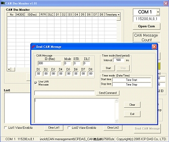
-
It has a CAN message field which can display the receiving CAN messages in Decimal or HEX mode.
-
Can display the timestamp of each received CAN message.
-
Users can change the display mode, up-down, down-up or stop.
-
It can count the number of received CAN messages.
-
Data Log : It can save the CAN message as “ txt ” file.
-
Has CAN ID filter function.
-
Can send CAN message to CAN BUS according the defined interval time.
|
|
| |
|
|
|
|
|
| |
|
|
| |
|
|
| |
| Item |
Description |
CAN bus Power Meter |
This is the software solution for the CAN bus power meter(PM-213x-CAN). It is convenient to collect the distributed power information via CAN bus. [more...] |
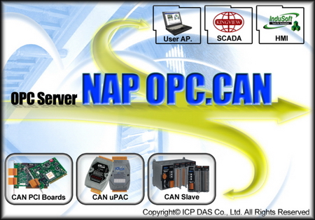
CAN OPC Server |
This is the OPC server for all the SCADA like LabVIEW, iFix, DASYLab and etc. By using the OPC server, the users be able to control any CAN devices via the famous SCADA. [more...] |
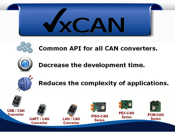
VxCAN Driver |
The VxCAN driver is the virtual CAN driver for all CAN converters and CAN master products. Even using different products, the users could use the same APIs to develop any CAN applications. [more...] |

InduSoft Driver |
The IndoSoft is one of the famous and high performance SCADA. Nowaday, it supports the CAN, CANopen and DeviceNet driver for all the coresponding converter or master series products. [more...] |
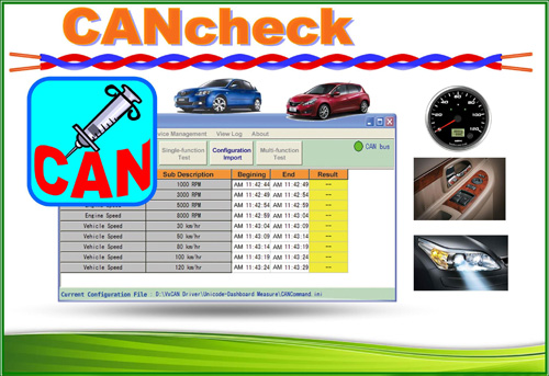
CANcheck |
This is the software for diagnosing and testing the user's CAN devices. The graphical interface is ready-made and easy to operate. [more...] |

CAN Test Tool |
The CAN test tool can help users to test the CAN communication of CAN series of ICP DAS by the simple steps. This tool is based on VxCAN driver and supports most of all CAN products of ICP DAS [more...] |
|
|
| |
|
|
|
|
|
| |
|
|
| |
|
|
| |
The test is the performance which transfer 8 bytes data frame from CAN to RS232. (for I-7530/I-7530T)
|
CAN setting |
Transfer frames |
Transfer time(ms) |
RS-232 setting |
Receive frames |
Receive time (ms) |
The max frames/sec |
Data<8 byes/frme |
RS232 command length |
2.0A 1Mbps |
1,000 |
200 |
115200,n,8,1 |
1,000 |
2954 |
338 |
>=338 |
22 B |
2.0A 1Mbps |
1,000 |
200 |
115200,n,7,1 |
1,000 |
2775 |
360 |
>=360 |
22 B |
2.0B 1Mbps |
1,000 |
200 |
115200,n,8,1 |
1,000 |
3580 |
279 |
>=279 |
27 B |
2.0B 1Mbps |
1,000 |
200 |
115200,n,7,1 |
1,000 |
3337 |
299 |
>=299 |
27 B |
The test is the performance which transfer 8 bytes data frame from RS232 to CAN. (for I-7530/I-7530T) |
CAN setting |
Transfer frames |
Transfer time (ms) |
RS-232 setting |
Receive frames |
Receive time (ms) |
The max frames/sec |
Data<8 byes/frame |
RS232 command length |
2.0A 1Mbps |
1,000,000 |
2,612,243 |
115200,n,8,1 |
1,000,000 |
2,612,243 |
382 |
>=382 |
22 B |
2.0A 1Mbps |
1,000,000 |
2,441,130 |
115200,n,7,1 |
1,000,000 |
2,441,130 |
409 |
>=409 |
22 B |
2.0B 1Mbps |
1,000,000 |
3,142,043 |
115200,n,8,1 |
1,000,000 |
3,142,043 |
318 |
>=318 |
27 B |
2.0B 1Mbps |
1,000,000 |
3,142,043 |
115200,n,7,1 |
1,000,000 |
2,966,646 |
337 |
>=337 |
27 B |
|
|
| |
|
|
|
|
|
| |
|
|
| |
|
|
| |
|
I-7530 |
I-7530T |
I-7530-FT |
Hardware |
EEPROM |
2 KB (for system information), 100,000 erase/write cycles |
CAN Interface |
Transceiver |
NXP 82C250 |
NXP TJA1042 |
AMIS 41682 |
Channel number |
1 |
Connector |
9-pin male D-Sub (CAN_L, CAN_H, N/A for others) |
Baud Rate (bps) |
10 k, 20 k, 50 k, 125 k, 250 k, 500 k, 800 k, 1 Mbps |
10 k, 20 k, 50 k, 125 kbps |
Isolation |
3000 VDC for DC-to-DC,
2500 Vrms for photo-couple |
NONE |
Terminator Resistor |
Selectable 120Ω terminator resistor by jumper |
1 kΩ for CAN_H and CAN_L |
Specification |
ISO-11898-2, CAN 2.0A and CAN 2.0B |
ISO-11898-3 (low speed fault tolerance), CAN 2.0A and CAN 2.0B |
Receive Buffer |
1000 data frames |
RS-232 Interface |
Connector |
9-pin female D-Sub (TxD, RxD, GND, N/A for others ) |
Baud Rate (bps) |
110, 150, 300, 600, 1200, 2400, 4800, 9600, 19200, 38400, 57600, 115200bps |
Data bit |
5, 6, 7, 8 |
Stop bit |
1, 2 |
Parity bit |
None, Even, Odd |
Receive Buffer |
900 data frames |
LED |
Round LED |
ON LED: Power and Data Flow; ERR LED: Error Status |
Power |
Protection |
Power reverse polarity protection, Over-voltage brown-out protection |
Power Consumption |
1 W |
Mechanism |
Installation |
DIN-Rail |
Dimensions |
72mm x 118mm x 33mm (W x L x H) |
Environment |
Operating Temp. |
-25 ~ 75 ℃ |
Storage Temp. |
-30 ~ 80 ℃ |
Humidity |
10 ~ 90% RH, non-condensing |
|
|
| |
|
|
|
|
|
| |
|
|
| |
|
|
| |
I-7530-G |
Intelligent RS-232 to CAN converter |
I-7530-G CR |
Intelligent RS-232 to CAN converter (RoHS) |
I-7530T-G CR |
Intelligent RS-232 to CAN converter (RoHS) |
I-7530-FT |
Intelligent RS-232/CAN low speed fault tolerant converter |
I-7530-FT CR |
Intelligent RS-232/CAN low speed fault tolerant converter (RoHS) |
|
|
| |
|
|
|
|
|
| |
|
|
| |
|
|
| |
|
CAN bus Connector |
|
9-pin Female D-sub & 3-wire CAN bus cable (1M) |
|
7/14 channel Surge Protector |
|
EMI Ferrite Split/Snap-On Core
|
|
Field-Installation A-coded 5-pin Female
|
|
|
| |
|
|
| |
|
|
|
|

