|
|
 |
|
| |
|
|
|
| |
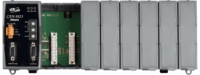
CAN-8823 ~ NEW ~
CANopen Remote I/O Unit with 8 I/O Expansions |
|
|
| |
|
|
|
|
|
|
|
|
| |
|
|
| |
CANopen, a kind of communication protocols,
is based on the intelligent field bus (CAN bus). It was developed
as a standardized embedded network with highly flexible configuration
capabilities. It provides standardized communication objects
for real-time data (Process Data Objects, PDO), configuration
data (Service Data Objects, SDO), network management data (NMT
message, and Error Control), and special functions (Time Stamp,
Sync message, and Emergency message). By now, CANopen is used
in many various application fields, such as medical equipment,
off-road vehicles, maritime electronics, public transportation,
building automation and etc.
CAN-8823 main control unit is specially designed for the slave
device of CANopen protocol. It follows the CANopen Spec DS-301
V4.02 and DSP-401 V2.1, and supplies many features for users,
such as dynamic PDO, EMCY object, error output value, SYNC cyclic
and acyclic, … and etc. In order to expand I/O channel more
flexible, an CAN-8823 supports up to 8 slots for I/O expansion
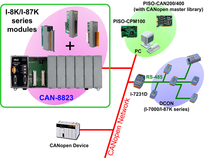
and suits with a lot of ICP DAS DI / AI / DO / AO modules. User
can choose DI/DO/AI/AO modules of I-87K series or I-8000 series
to fit the customized practice applications. In addition, we also
provide CAN-8823 Utility to allow users to create the EDS file dynamically.
The EDS file is based on CANopen DSP-306 and can be compatible
with different CANopen master interfaces. The application architecture
is as follows.
|
|
|
|
| |
|
| |
|
| |
CAN-8823 can automatically
scan the I-8K/I-87K IO modules plugged in the main unit and assigned
these modules to the specific application. Before users apply
the CAN-8823 in CANopen applications, they must understand the relationship
between these CANopen application and device object dictionary
in CAN-8823.
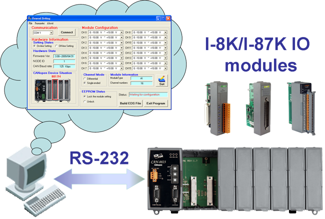
We also provide the CAN-8823 Utility tool to allow users
to make the configuration of AI/AO modules and some CANopen communication
parameters, such as Rx and Tx PDO mapping, error control, and
device object dictionary. After finishing
the Utility configuration, it will create the EDS file for the
connected CAN-8823 device. Furthermore, the EDS file of the CAN-8823
is not needed for the application, user can use the default configuration
for general DI/DO/AI/AO. And users only need to set the Node ID
and baud by hardware rotary switch. Then, after wire connection
and the CAN-8x23 powered on, it can work normally on the CAN bus
network through CANopen protocol.
|
|
|
| |
|
|
|
| |
|
|
| |
|
|
| |
The following simple steps show how
to use CAN-8823 in the CANopen protocol.
 |
|
| |
|
|
|
|
|
| |
|
|
| |
|
|
| |
•Industrial Machinery •Laboratory
Equipment & Research •Restaurant Appliances
•Maritime •Medical •Specialty Vehicles...etc.
 |
| |
|
|
|
| |
|
| |
|
| |
NMT |
Slave |
Error
Control |
Node Guarding and Heartbeat Producer protocol |
No.
of PDOs |
16Rx , 16Tx |
PDO
Modes |
Event Triggered,
Remotely requested, Cyclic and acyclic SYNC |
PDO
Mapping |
Avaiable |
No.
of SDOs |
1 server, 0
client |
Emergency
Message |
yes |
CANopen
Version |
DS-301 v4.02 |
Device
Profile |
DSP-401 v2.1 |
Baud
Rate Setting by Rotary Switch |
10K, 20K, 50K,
125K, 250K, 500K, 800K, and 1Mbps |
Node ID setting by Rotary Switch |
yes |
Produce
EDS file Dynamically |
yes |
ERR, RUN,and PWR LED |
yes |
|
| |
|
|
|
|
| |
|
| |
|
| |
Hardware |
CPU |
80186, 80 MHz or compatible |
SRAM/Flash/EEPROM |
512 KB / 512 KB / 2 KB |
NVRAM |
31 bytes (battery backup, data valid for up to 10 years) |
RTC (Real Time Clock) |
Yes |
Watchdog |
Watchdog IC |
Expansion Slot |
8 slots |
CAN Interface |
Controller |
NXP SJA1000T with 16 MHz clock |
Transceiver |
NXP 82C250 |
Connector |
5-pin screwed terminal block (N/A, CAN_L, CAN_SHLD, CAN_H, N/A) |
Baud Rate (bps) |
10 k, 20 k, 50 k, 125 k, 250 k, 500 k, 800 k, 1 M (By rotary switch) |
Transmission Distance (m) |
Depend on baud rate (for example, max. 1000 m at 50 kbps ) |
Isolation |
3000 VDC for DC-to-DC, 2500 Vrms for photo-couple |
Terminator Resistor |
Jumper for 120 Ω terminator resistor |
Specification |
ISO-11898-2, CAN 2.0A |
Protocol |
CANopen DS-301 ver4.02, DS-401 ver2.1 |
UART Interface |
COM 1 |
RS-232 (For configuration) |
LED |
Round LED |
PWR LED, RUN LED, ERR LED |
Power |
Power supply |
Unregulated +10 ~ +30 VDC |
Mechanism |
Dimensions |
188mm x 312mm x 91mm (W x L x H) |
Environment |
Operating Temp. |
-25 ~ 75 ℃ |
Storage Temp. |
-30 ~ 80 ℃ |
Humidity |
10 ~ 90% RH, non-condensing |
|
| |
|
|
|
| |
|
| |
|
| |
Type |
I-8K Series I/O |
I-87K Series I/O |
Type |
I-8K Series I/O |
I-87K Series I/O |
High Profile |
High Profile |
High Profile |
High Profile |
AI module |
I-8017HW |
I-87005W |
DI module |
I-8040W |
I-87040W |
I-8017HS |
I-87013W |
I-8040PW |
I-87040PW |
|
I-87015W |
I-8046W |
I-87046W |
|
I-87015PW |
I-8048W |
I-87051W |
|
I-87016W |
I-8051W |
I-87052W |
|
I-87017W |
I-8052W |
I-87053W |
|
I-87017W-A5 |
I-8053W |
I-87053PW |
|
I-87017RW |
I-8053PW |
I-87053W-A5 |
|
I-87017RCW |
I-8058W |
I-87053W-AC1 |
|
I-87018W |
|
I-87053W-E5 |
|
I-87018RW |
|
I-87058W |
|
I-87018ZW |
|
I-87059W |
|
I-87019RW |
|
|
DO module |
I-8037W |
I-87041W |
AO module |
I-8024W |
|
I-8041W |
I-87057W |
|
I-87024W |
I-8041AW |
I-87064W |
|
|
I-8056W |
I-87065W |
DI & DO module |
I-8042W |
I-87054W |
I-8057W |
I-87066W |
I-8050W |
I-87055W |
I-8060W |
I-87068W |
I-8054W |
I-87063W |
I-8064W |
I-87069W |
I-8055W |
|
|
|
I-8063W |
|
|
|
|
|
I-8068W |
|
Counter module |
I-8084W |
|
I-8069W |
|
PWM module |
I-8088W |
|
|
| |
|
|
|
|
|
| |
|
|
| |
|
|
| |
CAN-8823-G |
CANopen
Remote I/O Unit with 8 Expansions |
|
|
| |
|
|
|
|
|
| |
|
|
| |
|
|
| |
|
EMI Ferrite Split/Snap-On Core
|
|
Field-Installation A-coded 5-pin Female
|
|
|
| |
|
|
| |
|
|
|
|