| |
|
|
| |
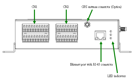
PIN Assignment |
|
| |
|
|
| |
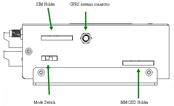
Bottom View: |
|
| |
 |
|
| |
|
|
| |
Left Side View: |
|
| |
 |
|
| |
|
|
| |
| CN1 Pin Assignment |
| Frame Ground |
F.G. |
Pin1 |
Pin11 |
N.C. |
|
| Power Input:+10~30Vdc |
DC.GND |
Pin2 |
Pin12 |
DC.GND |
Power Input:
+10~30VDC |
| DC.+VS |
Pin3 |
Pin13 |
DC.+VS |
| Ground For COM1 |
GND |
Pin4 |
Pin14 |
TxD1 |
COM1 RS-232 |
| COM2 RS-485 |
D- |
Pin5 |
Pin15 |
RxD1 |
| D+ |
Pin6 |
Pin16 |
RTS1 |
| Digital Output |
DO0 |
Pin7 |
Pin17 |
CTS1 |
|
| DO1 |
Pin8 |
Pin18 |
GND |
COM3 RS-232 |
| DO2 |
Pin9 |
Pin19 |
TxD3 |
| DO.PWR |
Pin10 |
Pin20 |
RxD3 |
|
|
| |
|
|
| |
| CN2 Pin Assignment |
| Digital Input |
DI0 |
Pin1 |
Pin9 |
AI0 |
Analog Input |
| DI1 |
Pin2 |
Pin10 |
AI1 |
| DI2 |
Pin3 |
Pin11 |
AI2 |
| GND |
Pin4 |
Pin12 |
AI3 |
| Analog Ground |
AGND |
Pin5 |
Pin13 |
AI4 |
| AGND |
Pin6 |
Pin14 |
AI5 |
| AGND |
Pin7 |
Pin15 |
AI6 |
| AGND |
Pin8 |
Pin16 |
AI7 |
|
|
| |
|
|
| |
Mode Switch |
|
| |
| Operation Mode Switch |
| RUN |
OS can execute autoexec.bat |
| Flash can be read/wirte. |
| Lock |
OS can execute autoexec.bat |
| Flash is read only (lock). |
| INIT |
OS can not execute autoexec.bat |
| Flash can be read/wirte. |
|
|
| |
|
|
|
|
|
| |
back |
|
| |
|
|
| |
Wire Connection |
|
| |
|
|
| |
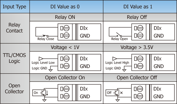
Digital Input Wire Connection |
|
| |
 |
|
| |
|
|
| |
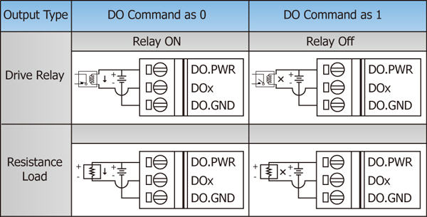
Digital Output Wire Connection |
|
| |
 |
|
| |
|
|
| |
Current Input Wire Connection |
|
| |
 |
|
| |
|
|
| |
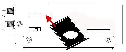
SIM Card Installation |
|
| |
 |
|
| |
|
|
| |
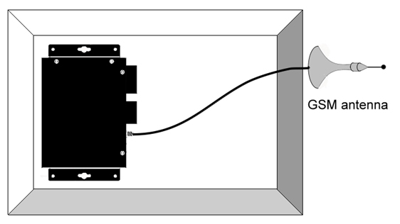
GPRS/GSM Antenna Installation |
|
| |
 |
|
| |
|
|
| |
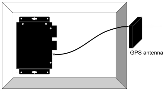
GPS Antenna Installation |
|
| |
 |
|
| |
|
|
|
|
|
| |
back |
|
| |
|
|
