The DAS-8421 / DAS-8821 is a multi-channel high-speed data acquisition system built on a real-time multitasking operating system architecture and based on Gigabit Ethernet communication. By using different high-speed data acquisition modules, it can meet customers' needs for high-speed and real-time data acquisition and analysis.
The high-performance data processing capability of the host hardware allows the collected data to be continuously streamed back to the PC for high-speed large data acquisition. The PC provides an SDK library for receiving data according to different scenarios and transmitting it to the customer’s application software or development programs. Additionally, this host supports the Modbus/TCP Slave communication protocol, enabling the PC to collect data from the modules on the acquisition host using the Modbus/TCP communication protocol in a polling manner.
A variety of software development tools are provided to facilitate customer development in different operating system environments. For Windows systems, VC, C#, VB.NET, .Net SDK, sample programs, and examples are offered. For Linux systems, C/C++, .Net libraries, and sample programs are available. Python and .Net libraries and sample programs are also provided, connecting to the DAS-8000 for high-speed data analysis, enabling diverse and customized applications.
Features
- Multi-channel I/O high-speed data acquisition
- 4/8 I/O slots
- Rich I/O module types
- Flexible I/O expansion architecture
- Built-in dual watchdog mechanism
- Supports TCP streaming and Modbus/TCP
- Host-side development program-free
- Fanless cooling
- Operating temperature -25 ~ +75 °C
The DAS-8000, paired with specific I-8K Analog Input modules, allows all channels to be sampled simultaneously.

The multi-channel high-speed data acquisition system and the high-speed synchronous data acquisition module use a common software development method (shared SDK and related demo)


DAS-8000 Operation Mode
1. High-Speed Multi-Channel Acquisition Mode
Only high-speed Analog Input modules can be installed into the host slot.

Applicable modules: I-8014W/I-8014CW/I-8012W
| Module | Resolution | Sampling mode | Trigger mode | Max. sampling Rate |
|---|---|---|---|---|
| I-8014W • 8 /16 channels • Voltage/current mode • Voltage/current can be set 16 channels (single-ended) |
16-bit | MagicScan interval scan sampling |
Software | 1 Hz ~ 250 kHz @ 1 channel 1 Hz ~ 35 kHz @ 32 channels 1 Hz ~ 15 kHz @ 64 channels 1 Hz ~ 6 kHz @ 128 channels |
| I-8014CW • 8 channels • Current mode |
16-bit | MagicScan interval scan sampling |
Software | 1 Hz ~ 250 kHz @ 1 channel 1 Hz ~ 35 kHz @ 32 channels 1 Hz ~ 15 kHz @ 64 channels |
| I-8012W • 8 channels • Voltage mode • Simultaneously sampling for all analog input channel |
16-bit | Simultaneously sampled inputs |
Software Internal/ External clock trigger |
16 Hz ~ 200 kHz @ 1 channel 16 Hz ~ 35 kHz @ 32 channels 16 Hz ~ 15 kHz @ 64 channels |
Features
PC-side data transfer mode
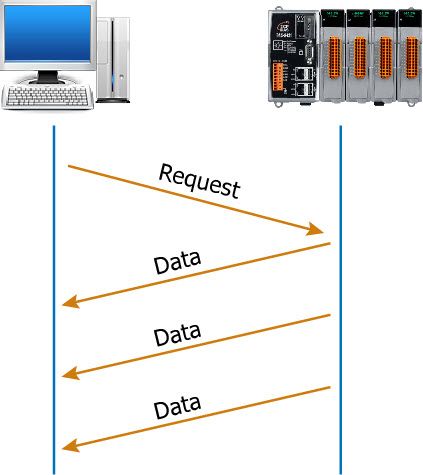
1. Continuous Transmission
After starting A/D acquisition, data is continuously transmitted to the Host PC.
In this mode of data acquisition, the host first sends a start acquisition command. The modules then stream large data packets one by one to the host until the host sends a stop acquisition command to halt data collection. Streaming mode is ideal for high sampling rates and large data transfer applications, enabling very rapid data acquisition. To maintain this fast rate, data must be buffered and sent back to the host in large packets from the device.
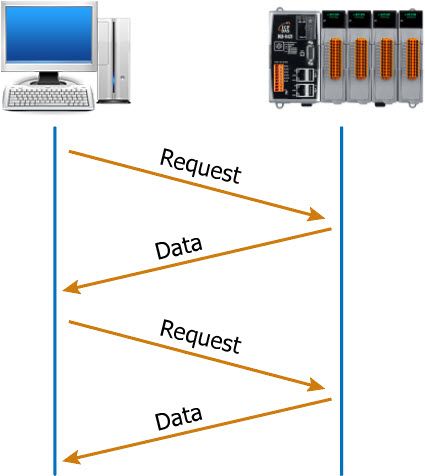
2. After collecting N data samples, the data is transferred to the Host PC
During A/D data acquisition, the data is initially stored in the memory of the DAS-8000. When a command is issued from the PC, the collected data is then transferred back to the PC. The modules operate in streaming mode, sending data packets one by one to the host until all buffered data is sent.In both modes, once the data is transferred to the PC, applications on the PC side must use the SDK library (HSDAQ) to access the high-speed acquisition data.
For more information about data transfer methods, please refer to Data Transmission Mode.
Applicable modules (I-8014W/I-8014CW/I-8012W), the internal sampling mode is
- Simultaneously sampled inputs – I-8012W
- MagicScan Interval Scan Sampling - I-8014W/I-8014CW
For more information about sampling modes, see Sampling Mode Comparison
Applicable modules (I-8014W/I-8014CW/I-8012W), supported trigger modes are
- Internal Software Trigger
Set the A/D acquisition parameters by issuing commands from the PC, and then trigger the command to start A/D acquisition of continuous or N pieces of data. - Internal Pacer Trigger
- External Pacer Trigger
The speed and number of data collected by the A/D are controlled by external electrical signals. The negative edge of each electrical signal triggers the A/D acquisition once.
For more information about trigger modes, see Trigger Mode Comparison
Applicable modules: I-8012W
If each module requires synchronous acquisition, an external synchronous acquisition signal (Clock) needs to be input to each module.
I-8012W multi-channel synchronous acquisition mode
1. The Master sends a synchronization trigger signal to the other Slave
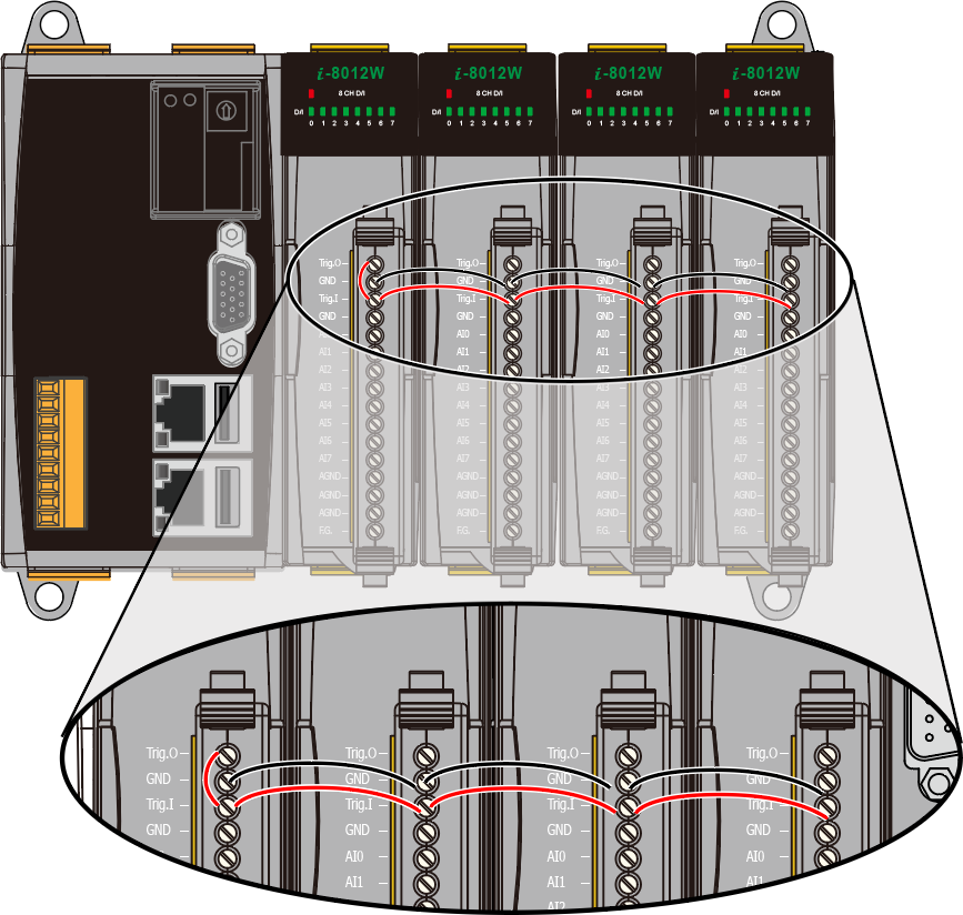
The first I-8012W is set as Master, and the others are set as Slave. The Trig.O output pin of the Master serves as an external synchronized acquisition signal source and is connected to the Trig.I pin of all I-8012W.
2. From the external signal output to the Trigger Input of each module

Access high-speed Analog Input channel number and Sampling Rate comparison
| Analog Input channels | Modules | Max. Sampling Rate |
|---|---|---|
| <= 8 | ET-2217H | 1 channel – 8 KHz |
| <= 8 | PET-7H16M | 8 channels – 30 KHz 1 channel – 200 KHz |
| > 8 ~ 128 | DAS-8000 + I-8012W | 64 channels – 15 KHz |
| DAS-8000 + I-8014W/ I-8014CW | 128 channels - 6 KHz |
* Maximum sampling speed achievable in continuous acquisition mode
2. Mixed Acquisition Mode
Different I-8K Analog IO/Digital IO modules can be mixedly inserted into the DAS-8000, Different ET-2000 AIO/DIO modules can be connected to increase the number of I/O points.
Scan rate between PC and DAS-8000 1 ~ 250 Hz.

Features
DAS-8x21 I/O Slots (4/8 Slots)
- Choose different types of I/O modules (I-8K) according to your needs
DAS-8x21 LAN2 Remote I/O Module
- ET-2000 series modules (8 pcs Max.)
- Automatically initialize modules and configure them in sequence
- Automatic scanning module, automatically assign IP address
- Easy PC-side Development. Access ET-2000 modules through DAS-8x21 without needing to connect to each ET-2000 individually.
Automatically define the Modbus/TCP memory (Register) address of I-8000 and ET-2000 modules.

The host size and different I/O combinations can be selected according to different channel number requirements, on-site wiring distance or installation space size.
If you need 24 RTD channels, 32 Thermocouple channels, 32 DI/DO channels, and 8 AO channels, you can use different I/O module combinations, such as the following two combinations

Users can choose different types of I/O modules according to their own needs, and install the modules in the slots of the DAS-8000 host or connect them to the LAN2 of the DAS-8000 through Ethernet. After the host is powered on, it will automatically initialize the module and configure the Modbus/TCP memory address in sequence. The user's PC software can read/write through the Modbus/TCP communication protocol.
1. High-Speed Acquisition Mode
The data transmission mode is the same as the first Analog Input high-speed multi-channel acquisition mode, with continuous transmission mode and N data samples transmission mode.
The module transmits data to the PC in streaming mode. PC applications need to use the SDK function library (HSDAQ) to obtain high-speed collected data.
2. Command Response Mode
Access the corresponding I/O address through Modbus/TCP protocol.
Software Trigger
Set the A/D acquisition parameters by issuing commands from the PC or host, and then trigger the command to start A/D data acquisition.
| Data Transmission Mode | Scanning rate between PC and Host |
|---|---|
| Continuous Transmission | 1 ~ 250 Hz |
| N data samples | 1 ~ 250 Hz |
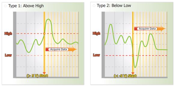
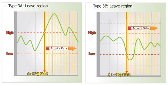
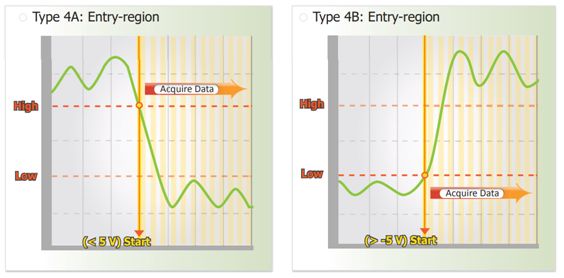
Analog Threshold Trigger
Analog threshold trigger is triggered when the voltage signal of the specified analog input channel is higher or lower than a certain voltage setting.
In addition, the user can also specify the trigger voltage level range of the input signal. Once the signal leaves the high and low level region or the signal enters the high and low level region, it is triggered to start the acquisition.
1. Above High:The signal is triggered above the high level setting
2. Below Low:The signal is triggered below the low level setting
3. Leave-region :Trigger when the signal leaves the high and low level region
4. Entry-region :Trigger when the signal enters the high and low level region
|
|
|||||||||
|
Ethernet multi-channel high-speed data acquisition system
The DAS-8000 series is a multi-channel high-speed data acquisition system based on Gigabit Ethernet communication. It offers flexibility and adaptability by incorporating different high-speed data acquisition. |
|||||||||
| Model | Ethernet | I/O Expansion | I-8K Series | Temperature | |||||
|---|---|---|---|---|---|---|---|---|---|
| DAS-8421 | 2(10/100/1000M) | 4 | Yes | Operating:-25 ~ +75 °C Storage:-30 ~ +80 °C |
|||||
| DAS-8821 | 8 | Yes | |||||||
Module that supports high-speed multi-channel acquisition mode (operation mode 1)
I-8K series Modules
| Module | Description | Max. Sampling Rate |
|---|---|---|
| I-8012W | 8 channels Voltage Input | 1 Hz ~ 250 kHz @ 1 channel 1 Hz ~ 35 kHz @ 32 channels 1 Hz ~ 15 kHz @ 64 channels 1 Hz ~ 6 kHz @ 128 channels |
| I-8014W | 8 /16 channel Voltage/Current Input | 1 Hz ~ 250 kHz @ 1 channel 1 Hz ~ 35 kHz @ 32 channels 1 Hz ~ 15 kHz @ 64 channels |
| I-8014CW | 8 channels Current Input | 16 Hz ~ 200 kHz @ 1 channel 16 Hz ~ 35 kHz @ 32 channels 16 Hz ~ 15 kHz @ 64 channels |
Modules that support Mixed Acquisition Mode (operation mode 2)
I-8K series Modules
| Module | Description | Feature | Scan Time |
|---|---|---|---|
| I-8015W | 8 channels RTD Input | - | 4 ms (250 Hz)/pcs |
| I-8015W-12 | 12channels RTD Input | - | 4 ms (250 Hz)/pcs |
| I-8018W | 8 channels Thermocouple Input | - | 4 ms (250 Hz)/pcs |
| I-8018W-16 | 16 channels Thermocouple Input | - | 4 ms (250 Hz)/pcs |
| I-8041W | 32 channels Digital Output | - | < 1 ms/pcs |
| I-8060W | 6 channels Relay Output | Form C | < 1 ms/pcs |
| I-8064W | 8 channels Relay Output | Form A | < 1 ms/pcs |
| I-8040W | 32 channels Digital Input | - | < 1 ms/pcs |
| I-8024UW | 4 channels Analog Output | 16-bit | < 1 ms/pcs |
| I-8028UW | 8 channels Analog Output | 16-bit | < 1 ms/pcs |
| I-8014W | 8/16 channels Analog Input | 16-bit | < 1 ms/pcs |
ET-2000
| Module | Description | Feature | Scan Time |
|---|---|---|---|
| ET-2215 | 8 channels RTD Input | - | 3 ms/pcs |
| ET-2215-12 | 12 channels RTD Input | - | 3 ms/pcs |
| ET-2218 | 8 channels Thermocouple Input | - | 3 ms/pcs |
| ET-2218-16 | 16 channels Thermocouple Input | - | 3 ms/pcs |
| ET-2242 | 16 channels Digital Output | - | 3 ms/pcs |
| ET-2242-32 | 32 channels Digital Output | - | 3 ms/pcs |
| ET-2261 | 8 channels Relay Output | Form A | 3 ms/pcs |
| ET-2261-16 | 16 channels Relay Output | Form A | 3 ms/pcs |
| ET-2251 | 16 channels Digital Input | - | 3 ms/pcs |
| ET-2251-32 | 32 channels Digital Input | - | 3 ms/pcs |
| ET-2224CI | 4 channels Analog Output | 16-bit | 3 ms/pcs |
| ET-2228CI | 8 channels Analog Output | 16-bit | 3 ms/pcs |
| ET-2217CI | 8/16 channels Analog Input | 16-bit | 3 ms/pcs |
Applications
- Multi-channel high-speed acquisition
- Multi-channel distributed data acquisition applications
- Mixed-signal data acquisition
Applicable Scenarios
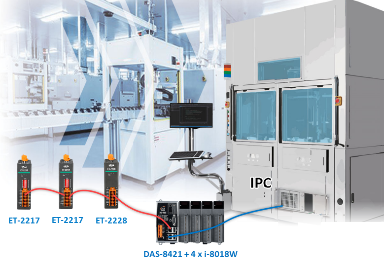
Semiconductor Equipment Applications
Active Temperature Control (ATC) systems are an indispensable component in modern semiconductor IC testing machines. ATC systems can achieve precise and stable temperature control, ensuring optimal component performance, improving test accuracy, shortening test cycle times, and optimizing energy consumption. This makes them a reliable and efficient tool for semiconductor IC testing, especially in applications involving rapid temperature changes.
System Composition
DAS-8421 x 1 , i-8018W x 4 , ET-2228 x 1 , ET-2217 x2
- DAS-8421:Equipped with 4 slots for installing 4 I-8018W modules, it connects multiple remote ET-2200 modules via LAN2. The host exchanges data rapidly with each module and uses TCP streaming to quickly send data back to the upper-level PC.
- I-8018W :An 8-channel high-speed thermocouple input module, it provides real-time temperature data from various positions of the machine to the temperature control system, allowing adjustments to heating and cooling elements as needed to maintain the required temperature curve.
- ET-2228:An 8-channel analog output module that controls the flow switches of the temperature control system.
- ET-2217:An 8-channel analog input module that measures flow values.
- ET-2217:Measures the voltage values of the test objects.
Advantages
- 32-channel thermocouple temperature measurement, each channel providing a 100 Hz sampling rate, with each channel independently configurable for input type.
- Flexible centralized & distributed deployment of modules based on the machine's functional characteristics and space constraints.
- The DAS-8000 host actively accesses data from both the local and remote modules, allowing the PC software to connect to just one host to read all module data, eliminating the need to connect and access multiple remote modules.