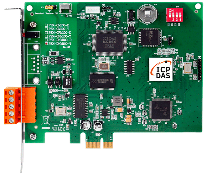
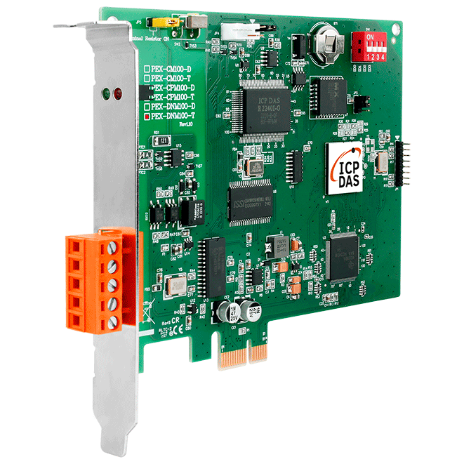
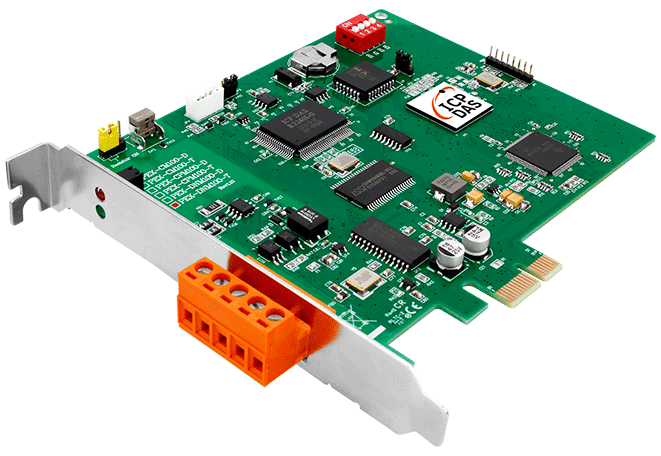
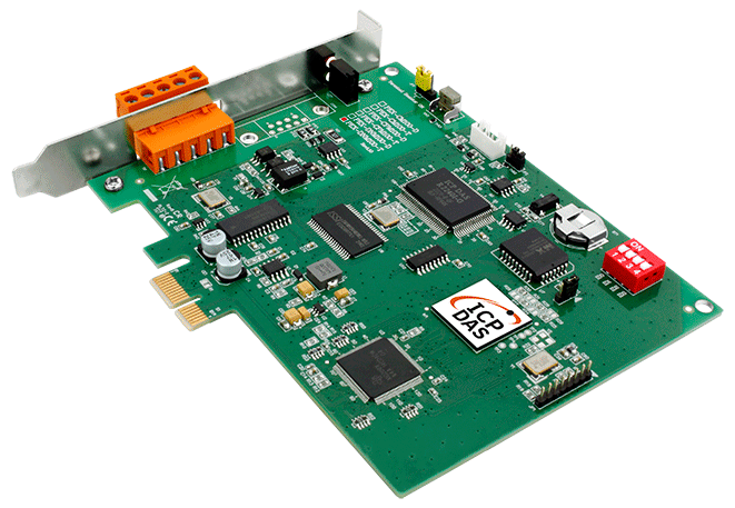
PEX-DNM100-T
1 Port Intelligent DeviceNet Master PCI Express Board
Features
- DeviceNet Version: Volume I & II, Release 2.0
- Programmable Master MAC ID and Baud Rate
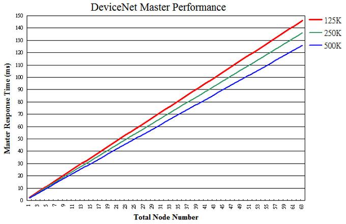
- Baud Rate: 125 kbps, 250 kbps, 500 kbps
- Support Group 2 and UCMM connection
- I/O Operating Modes: Poll, Bit-Strobe, Change of State / Cyclic
- I/O Length: 512 Bytes max (Input/Output) per slave
- Slave Node : 63 nodes max
- Support Auto-Search slave device function
- Support on-line adding and removing devices
- Support Auto-detect Group 2 and UCMM device
- Auto-Reconnect when the connection is broken
Introduction
The PEX-DNM100 can represent an economic solution of DeviceNet application and be a DeviceNet master device on the DeviceNet network. It is a "Predefined Master-Slave connection Set". The PEX-DNM100 supports Group 2 only Server and UCMM functions to communication with slave devices. It has an independent CAN bus communication port and has the ability to cover a wide range of DeviceNet applications.
Besides, the PEX-DNM100 uses the CAN controller NXP SJA1000, which provide bus arbitration, error detection with auto correction and re-transmission function.It can be installed on almost any windows-based system, for example Windows system. It is popularly applied in the industrial automation, building automation, vehicle, marine, and embedded control network. In order to expand the DeviceNet functions of ICPDAS products, the PEX-DNM100 is developed for this purpose.
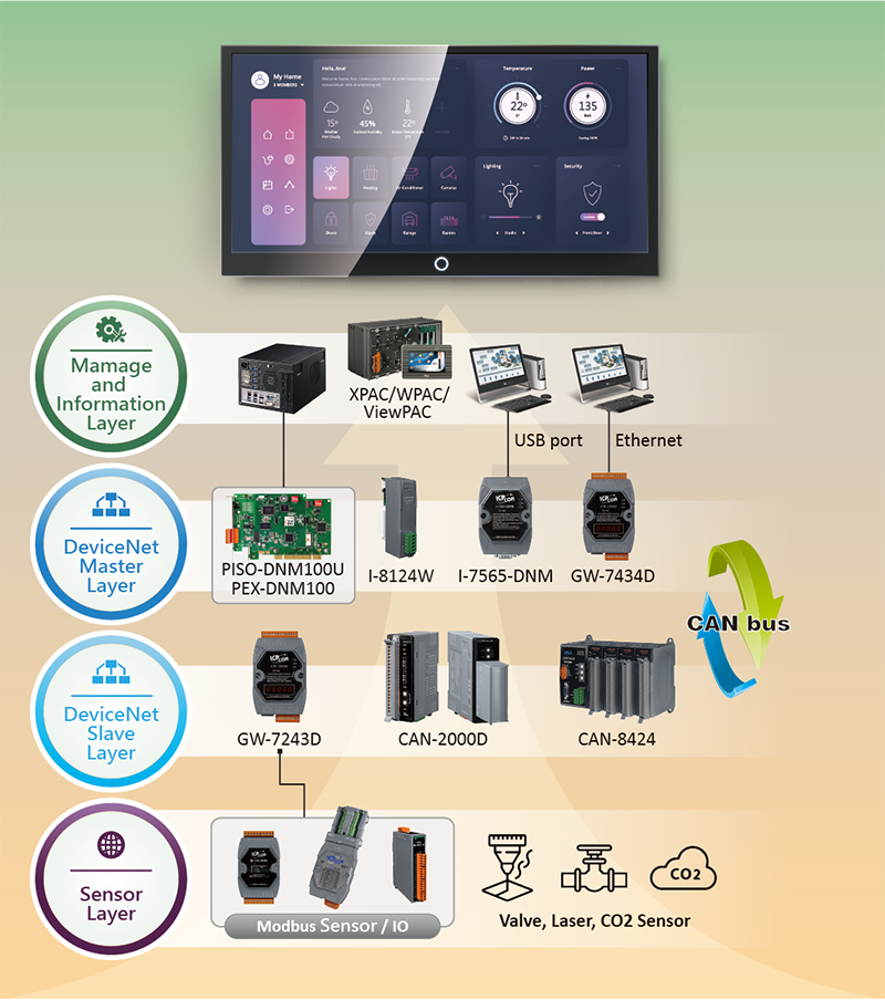
Applications
Ordering Information
| PRODUCT SERIES | DESCRIPTION | QNT. | INQUIRY |
|---|---|---|---|
Similar Products
| Software | |
|---|---|
| Driver | Windows XP/7/8/10 (32-bit/64-bit OS) |
| SDK | VB 6.0, VC++ 6.0, BCB 6.0, Visual Studio .NET |
| LED Indicators | |
|---|---|
| Status | Green LED, Red LED |
| PC Bus | |
|---|---|
| Type | PCI Express bus |
| Board No. | By DIP switch |
| DeviceNet | |
|---|---|
| Controller | NXP SJA1000T Built-in Microprocessor |
| Ports | 1 |
| Baud Rate | 125 k, 250 k, 500 k |
| Isolation | 3000 VDC for DC-to-DC, 2500 Vrms for photo-couple |
| Terminal Resistor | Jumper for 120 Ω terminal resistor |
| Protocol | DeviceNet Volumn I ver2.0, Volumn II ver2.0 |
| CAN Specification | ISO-11898-2, CAN 2.0A and CAN 2.0B |
| Power | |
|---|---|
| Consumption | 300 mA @ 5 V |
| Mechanical | |
|---|---|
| Dimensions (mm) | 133 x 22 x 98 (W x L x H) |
| Environment | |
|---|---|
| Operating Temperature | 0 ~ +60 ℃ |
| Storage Temperature | -20 ~ +70 ℃ |
| Humidity | 5 ~ 85% RH, Non-condensing |
There exist two memory areas, “Input Area” and “Output Area”. The input data of all DeviceNet slaves would be stored in the “Input Area” by DeviceNet master scan engine. Oppositely, the output data of those DeviceNet slaves would be in the “Output Area”. Please refer to the following figure.
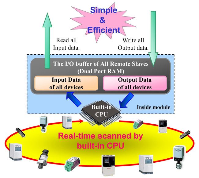
Users can read a bulk data from “Input Area” in the DeviceNet Master module, like PISO-DNM100U or I-8124W. This bulk data contains multiple devices’ input statuses. If one of the input status of the remote DeviceNet slave changes, the corresponding data located in the “Input Area” would change immediately. Oppositely, the “Output Area” contains multiple devices’ output data. Users may change the output value of a certain device by changing the corresponding data located in the “Output Area”.
Performance Test