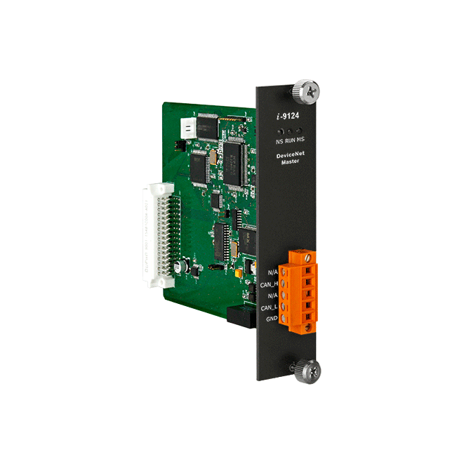
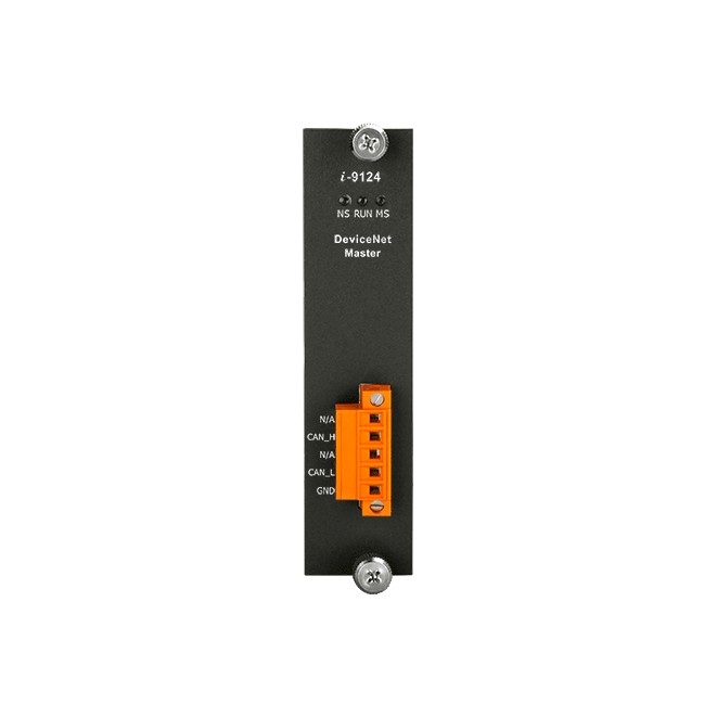
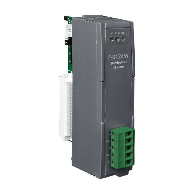
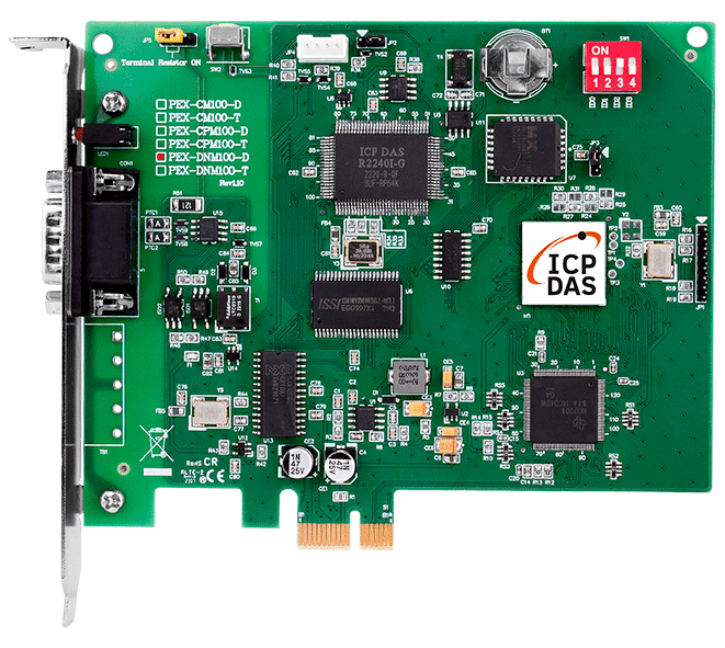
I-9124
1 Port High Performance DeviceNet Master Module


Features
- DeviceNet Version: Volume I & II, Release 2.0
- Programmable master MAC ID and baud rate.
- Baud Rate: 125k, 250k, 500k bps
- Support Group 2 and UCMM connection
- I/O Operating Modes: Poll, Bit-Strobe, Change of State / Cyclic
- I/O Length: max 512 input bytes and 512 output bytes per slave
- Slave Node : 63 nodes max.
- Auto-reconnect when the connection is broken
Introduction
CAN (Controller Area Network) is a serial communication protocol that supports distributed real-time control and has high security features. CAN is particularly suitable for networked "intelligent" devices and systems, or sensors and actuators in subsystems. In a CAN network, generally, there is no addressing of users or stations, but rather the sending of priority messages.
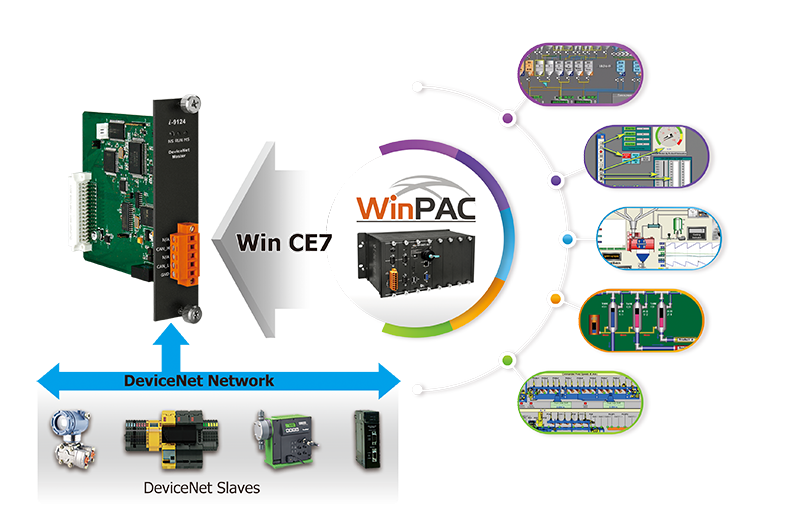
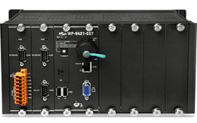
I-9124 is a DeviceNet master module that supports both Group 2 and UCMM functions, offering a high-performance DeviceNet master solution. Combined with the expansibility and flexibility of the WinPAC-9000-CE7 series host, I-9124 can be used in applications with higher real-time requirements. I-9124's firmware includes a complete set of DeviceNet communication protocol encoding and decoding functions. Application developers can use simple "Read" or "Write" commands to control the I/O data of remote DeviceNet slave devices. Thus, I-9124 not only expands the WinPAC-9000-CE7 series host with a DeviceNet communication interface but also assists users in efficiently monitoring remote DeviceNet slave devices without being familiar with the complex DeviceNet communication protocols.
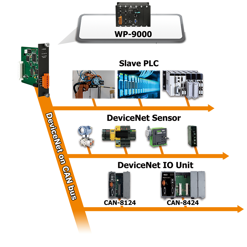
Applications
Ordering Information
| PRODUCT SERIES | DESCRIPTION | QNT. | INQUIRY |
|---|---|---|---|
Similar Products
| Software | |
|---|---|
| Driver | WP-9000-CE7 |
| SDK | For CE7: C#.Net, VC 2008 (with .Net Framework 3.5 or upper) |
| LED Indicators | |
|---|---|
| Status | NS LED, RUN LED, MS LED |
| DeviceNet | |
|---|---|
| Controller | NXP SJA1000T |
| Ports | 1 |
| Baud Rate | 125 k, 250 k, 500 k |
| Isolation | 3000 VDC for DC-to-DC, 2500 Vrms for photo-couple |
| Terminal Resistor | Switch for 120 Ω terminal resistor |
| Protocol | DeviceNet Volumn I ver2.0, Volumn II ver2.0 |
| CAN Specification | ISO-11898-2, CAN 2.0A and CAN 2.0B |
| Power | |
|---|---|
| Consumption | 1.5 W |
| Mechanical | |
|---|---|
| Dimensions (mm) | 31 x 133 x 145 (W x L x H) |
| Environment | |
|---|---|
| Operating Temperature | -25 ~ +75 ℃ |
| Storage Temperature | -30 ~ +80 ℃ |
| Humidity | 10 ~ 90% RH, Non-condensing |
Diagnosis
This utility supports to search all devices and specific devices in the network. These functions help the users to configure the connection of the slave devices. Anymore, the software also can diagnose the remote slave devices when building the DeviceNet network.
Configuration
Remote I/O access
The software utility can easily to access the I/O data of all the slave devices. The users can monitor the input data of the specific slave device and change the output data to the remote slave device with this utility.


Memory map of Remote I/O
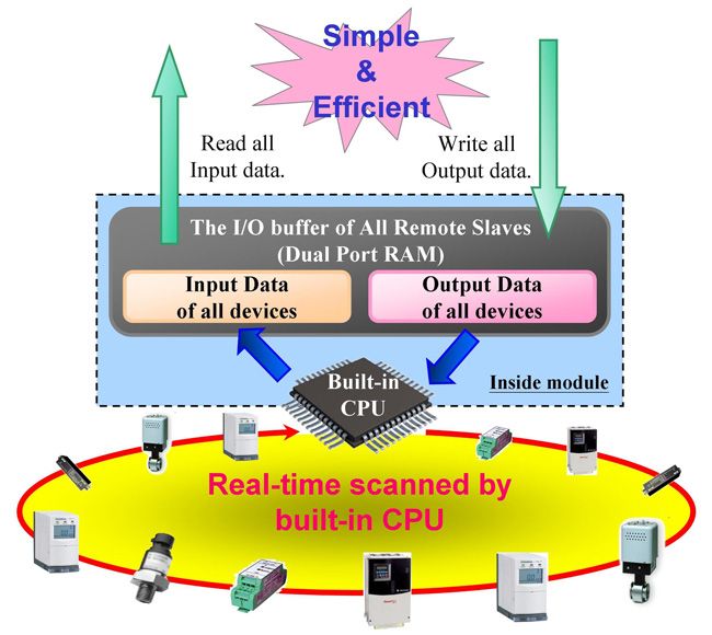
Users can read a bulk data from “Input Area” in the DeviceNet Master module, like I-9124. This bulk data contains multiple devices’ input statuses. If one of the input status of the remote DeviceNet slave changes, the corresponding data located in the “Input Area” would change immediately. Oppositely, the “Output Area” contains multiple devices’ output data. Users may change the output value of a certain device by changing the corresponding data located in the “Output Area”.