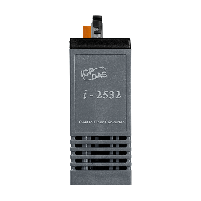
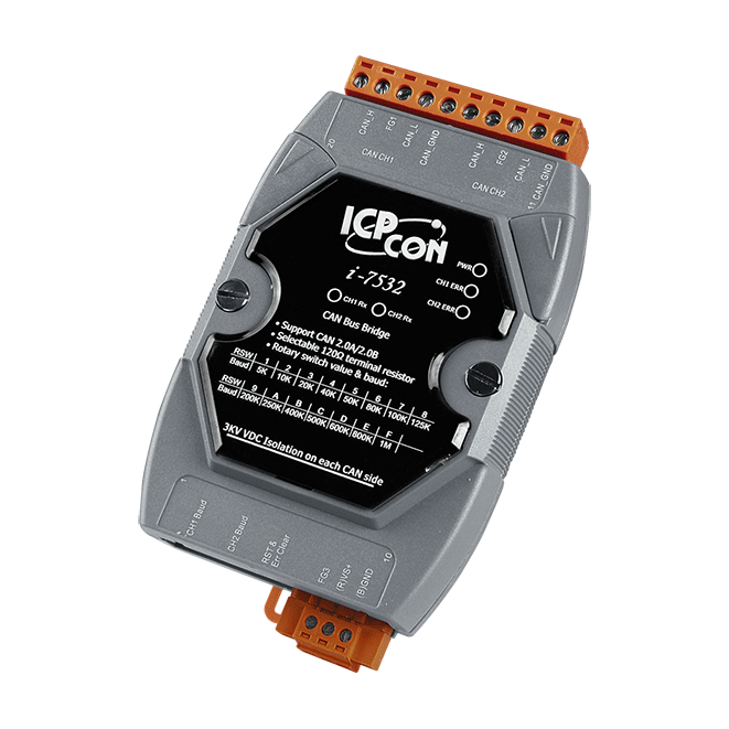
CAN to Multi-mode Fiber Converter
Features
- Compatible with CAN specification 2.0A and 2.0B
- Fully compatible with the ISO 11898-2 standard
- Support a range of baud rates from 10kbps ~ 500Kbps
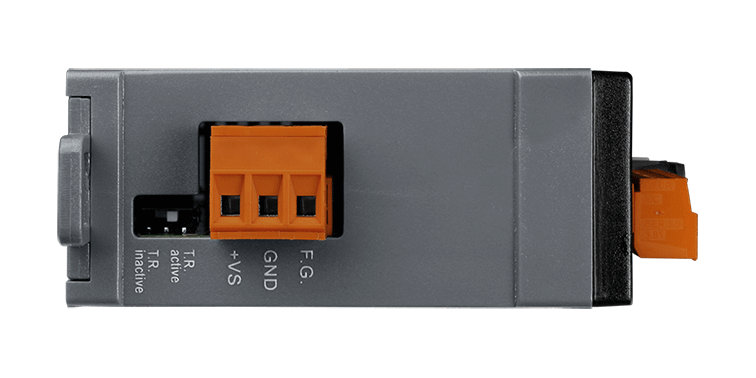
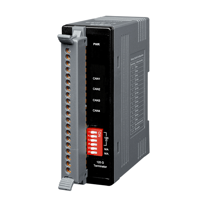
- Jumper for 120Ω terminal resistor of the CAN bus
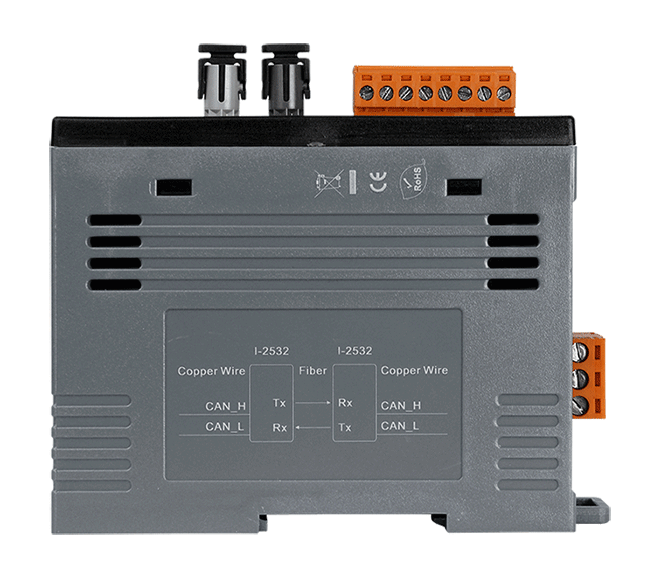
- Fiber Port: ST (Multi-mode)
- Fiber Cable: 50/125 μm , 62.5/125 μm, 100/140μm
- Wave Length: 850 nm
- Auto-baud detection
- up to 100 nodes on CAN port
- Removable terminal block
- Mount easily on DIN-rail
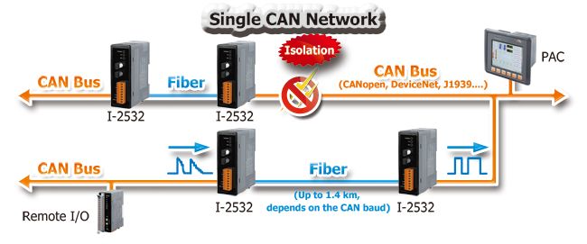
- 3 kv galvanic isolaton
- One CAN and one fiber channel
Introduction
Applications
- Control System
- Building Automation
- Factory Automation
- Distributed data acquisition
Ordering Information
| PRODUCT SERIES | DESCRIPTION | QNT. | INQUIRY |
|---|---|---|---|
Similar Products
| LED Indicators | |
|---|---|
| Status | 1 x Power 2 x CAN status |
| Fiber | |
|---|---|
| Ports | Multi Mode; ST connector x 1 |
| Fiber Cable | 50/125, 62.5/125 or 100/140 μm (62.5/125μm is recommended) |
| Wavelength | 850 nm |
| Transmission Distance | 1.4 km max (62.5 / 125 μm recommended) |
| Propagation Delay | 125ns max (125ns delay shortens bus line length by ~ 25 m) |
| CAN | |
|---|---|
| Ports | 1 |
| Specification | ISO-11898-2, CAN 2.0A and CAN 2.0B |
| Baud Rate | 10 k ~ 500 k bps |
| Terminal Resistor | Switch for 120Ω terminal resistor |
| Power | |
|---|---|
| Input Range | +10 VDC ~ +30 VDC |
| Consumption | 0.5 W |
| Mechanical | |
|---|---|
| Casing | Plastic |
| Dimensions (mm) | 32.3 x 77.5 x 99.0 (W x L x H) |
| Installation | DIN-Rail |
| Environment | |
|---|---|
| Operating Temperature | -25 ~ +75 °C |
| Storage Temperature | -30 ~ +80 °C |
| Humidity | 10 ~ 90% RH, Non-condensing |
The definition of segment in a CAN bus system are shown as following figure. The segment 2 is fiber cable. Generally, the segment 1 and segment 3 are copper cable. The copper cable is a balanced (differential) 2-wire interface. It may be a Shielded Twisted Pair (STP), Un-shielded Twisted Pair (UTP), or Ribbon cable.
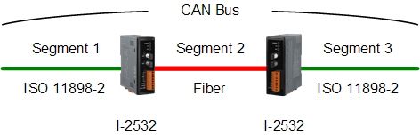
Users can refer to the following table to know the maximum node numbers in each segment following ISO 11898-2 and the maximum segment length when using different type of wire.
| Wire Cross- Section [mm2] |
The maximum segment length [m] under the case of specific node number in this segment |
|||
|---|---|---|---|---|
| 16 Nodes | 32 Nodes | 64 Nodes | 100 Nodes | |
| ~0.25 (AWG23) | < 220 | < 200 | < 170 | < 150 |
| ~0.5 (AWG20) | < 390 | < 360 | < 310 | < 270 |
| ~0.8 (AWG18) | < 590 | < 550 | < 470 | < 410 |
| ~1.3 (AWG16) | <980 | <900 | <780 | <670 |
Higher attenuation of fiber will reduce the transmission distance. Users can use following table to know the relationship between those two.
| Attenuation [dB/km] | Fiber Length [m] |
|---|---|
| 2.8 | <1400 |
| 4 | <400 |
The limitation of baud on a CAN bus system is restricted by propagation delay. On the other hand, long bus length leads to long propagation delay. The relationship between baud and bus length is displayed below.
| Baud [bit/sec] | Ideal Bus Length [m] |
|---|---|
| 500K | < 100 |
| 250K | < 250 |
| 125K | < 500 |
| 50K | < 1000 |
| 20K | < 2500 |
| 10K | < 5000 |
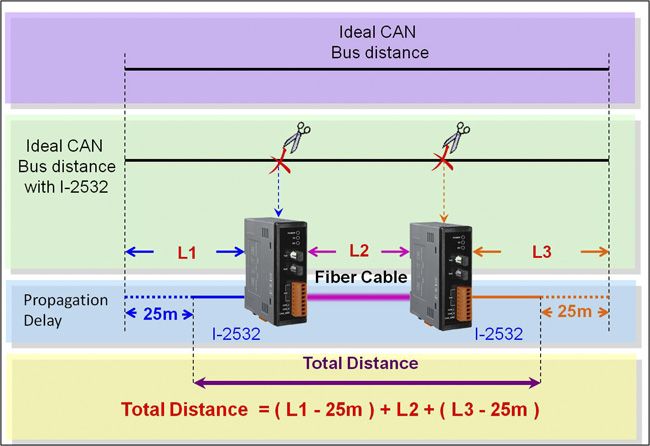
The definition of segments the relationship between segment length (LSEG1, LSEG2 …) and bus length (LBUS) in the same CAN bus system are shown in the following figure.
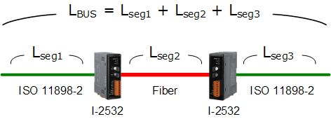
When users add one pair of I-2532 into a CAN bus system, the ideal bus length will reduce 50 meters because the propagation delay of one I-2532 is equal to the propagation delay caused by 25 meters bus length. For example, if users use baud 50Kbps and add two I-2532s into the CAN network, the ideal bus length should less than 950 meters (1000-25*2=950)