Sampling Mode Comparison
Sampling Mode
The sampling modes of Analog Input data acquisition modules are of three types:
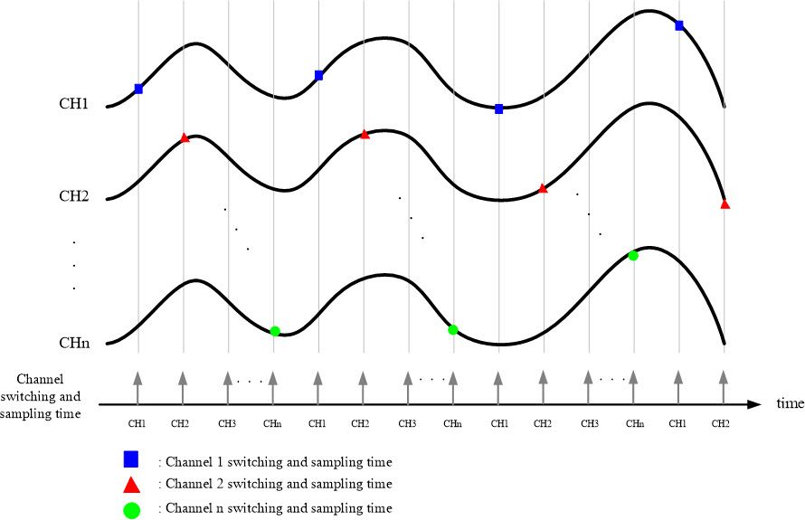
1. Simultaneously Sampled Inputs
Modules with this sampling mode provide precise sampling frequencies and use a sample-and-hold circuit to sample all channels simultaneously. Each channel has an independent amplifier, and the sampled values are sent to the ADC for conversion through a multiplexer, achieving simultaneous sampling for each channel. This method is highly suitable for applications requiring synchronized multi-channel signals.
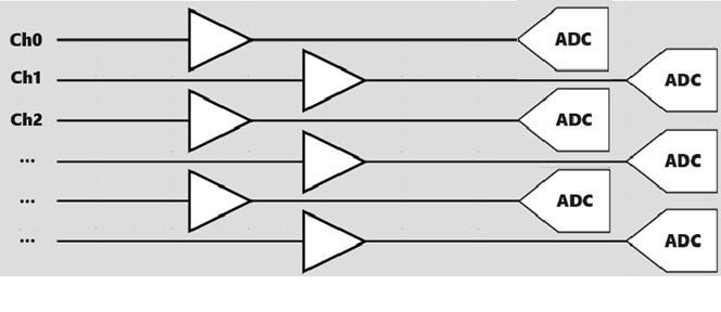 |
| Figure 1: Synchronous Scanning Sampling Diagram |
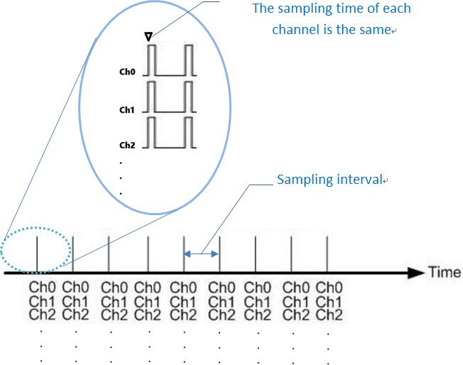 |
| Figure 2 Multi-channel synchronous scanning sampling chart |
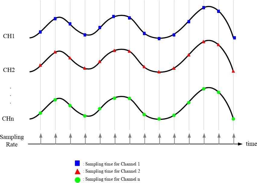 |
| Figure 3 Multi-channel synchronous scanning sampling timing diagram |
2. MagicScan interval scan sampling
This type of module from ICP DAS has a built-in MagicScan mechanism. The hardware consists of an ADC, a multiplexer and a MagicScan controller. This scanning mode automatically samples and stores ADC data directly into FIFO storage space, allowing the CPU host to read it directly without consuming CPU processing time.
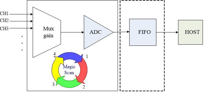 |
| Figure 4 MagicScan mechanism framework diagram |
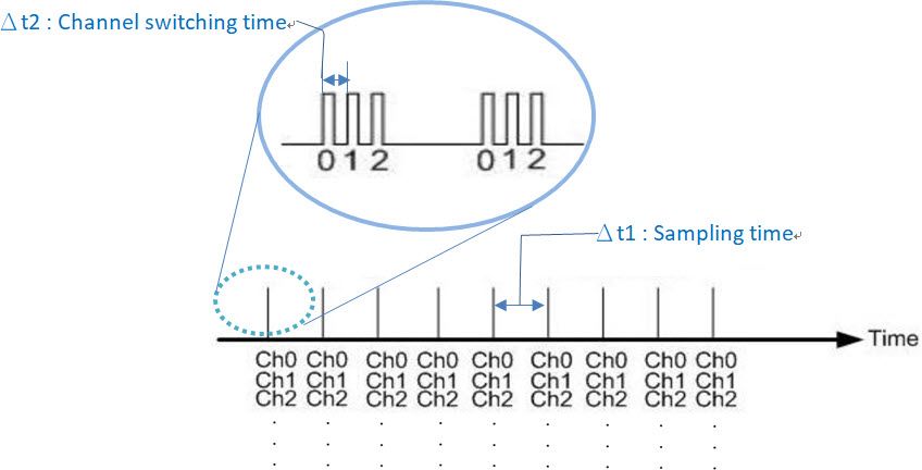
Magic Scan has two scanning sampling methods.
One is the standard mode, where precise sampling frequencies are sequentially applied to each channel for data acquisition. The sampling frequency can be adjusted according to requirements.
 |
| Figure 5: Multi-Channel MagicScan Interval Scanning Sampling Mode 1 |
 |
| Figure 6: Multi-Channel MagicScan Interval Sampling Timing Diagram Mode 1 |
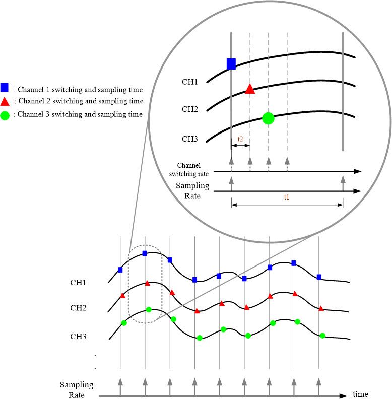
The second method is the Virtual Multi-Channel Synchronous Sampling (Virtual Sample and Hold) method.
During data acquisition, the sampling clock determines when to begin sampling. In each sampling period, the module samples all configured channels simultaneously. This method automatically switches between channels, ensuring stable time capture of signals from each channel. The switching time is fixed and very short. This sampling method is suitable when the relative timing between channels is not critical or when the sampling rate is high enough to ignore minor timing differences between channels.
 |
| Figure 7 Multi-channel MagicScan interval scanning sampling chart mode 2 |
 |
| Figure 8 Multi-channel MagicScan interval sampling timing diagram mode 2 |
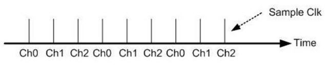
3. Polling scan sampling
This type of module uses a firmware-controlled sampling method, relying on an ADC (Analog-to-Digital Converter) and a multiplexer. In this mode, there is no sampling clock; instead, the firmware issues commands to sequentially switch channels and perform sampling. This means that the sampling time varies based on the command issuance timing. If the intervals between issuing commands are very stable, the sampling time will also be very stable. Conversely, if the command intervals are unstable, the sampling time will also become unstable.
This mode is particularly suitable for applications where the sampling rates of different channels need to be varied, or where some channels can have lower sampling rates than others. Additionally, this mode has a lower hardware cost.
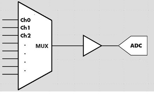 |
| Figure 9 Diagram of polling scan sampling |
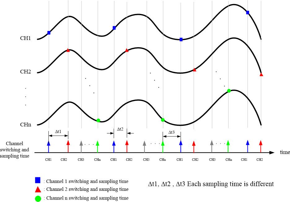 |
| Figure 10 Multi-channel polling scan sampling timing diagram |
- Simultaneous Scanning Sampling → Each data acquisition interval is identical, and the sampling time for each channel is also the same. This method is suitable for applications such as semiconductor equipment, sound, and vibration measurement.
- Interval Scanning Sampling → The sampling clock determines when to sample, ensuring that the time between each data acquisition is the same. Each channel has a small switching time.
- Polling scan sampling → No sampling clock, the sampling time and stability depend on whether the command interval time under the firmware is stable.
