|
|
 |
|
| |
|
 |
|
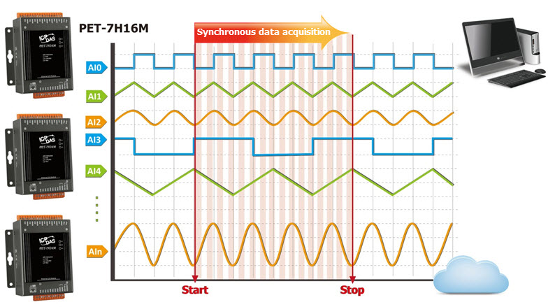
The PET-7H16M/PET-7H24M is a high speed data acquisition devices with a built-in POE Ethernet communication port for data transfer over a network. PET-7H16M includes 8 high-speed 16-bit single-ended Analog input channels (200 kHz sample and hold for all 8 channels) and PET-7H24M includes 4 high-speed 24-bit differential Analog input channels (128 kHz sample and hold for all 4 channels). All high speed data acquisition modules allow A/D signal conversion simultaneously on each channel and provide the programmable input range on all analog input channels. In addition to supporting Analog Input channels, the module also provides Digital Input / Digital Output / Counter / Encoder with different combinations and different numbers of channels.
The module provides a programmable input range on all analog Input channels, and the Digital Output can be set to output with short-circuit and overload protection. The counter value of DI counters and High-speed counter are latched by ADC sampling time synchronously. The Encoder Input channel can be configured as Quadrant, Pulse/Direction or CW/CCW input mode. The module provides 4 kV ESD protection as well as 2500 VDC intra-module isolation.
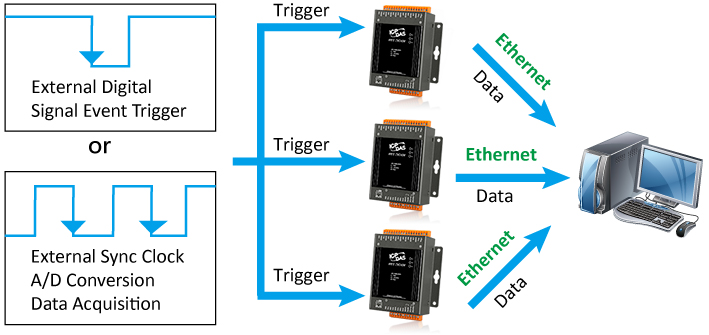
The PET-7H16M/PET-7H24M supports more kinds of trigger modes for A/D conversion: software A/D trigger, external clock trigger, external digital signal event trigger (Post-trigger/Pre-trigger/Delay-trigger) and analog trigger. The software trigger can acquire a sample whenever needed, and the continuous A/D acquisition or the acquisition of N data samples begins after the command is triggered. In external clock trigger mode, the speed of the A/D acquisition and the amount of data acquired are controlled by external electrical signals. In digital signal event trigger mode, the A/D acquisition parameters are configured via a command and the A/D acquisition of the N data samples is started while triggered by an external electrical signal. The analog trigger mode triggers when the analog input value is higher or lower than the set specific voltage value, and starts the A/D acquisition of the N data. |
|
|
|
 |
|
| |
|
1. High speed acquisition via Ethernet
Ethernet has many advantages such as standard reliability, easy installation, long transmission distance and fast transmission speed. Its openness and popularity are not only widely used in the integration of IT, enterprise and field, but also become the mainstream specification for industrial communication.
At present, most of the high-speed synchronous data capture systems are mostly collected by a computer host with data capture cards. When the number of channels increases, more data is needed to capture the card. If the devices to collect data are distributed across multiple sites, you will need to increase the number of computer hosts. At this time, the PET-7H16M/PET-7H24M is used instead of the configuration of the computer and data capture card. The data collected from different sites can be transmitted to the central monitoring computer through the network, which can greatly reduce the complexity and time cost of the built wiring, and has the advantages of real-time monitoring. Of device status and centralized data management. The module can be used for continuous data acquisition, high-speed interval acquisition, and simultaneous acquisition with multiple channels. The maximum acquisition speed of each AI channel can exceed 100 kHz. It is suitable for high-speed data acquisition of various mechanical, electronic and physical signals in industrial production, automatic control, electrochemistry, medicine, etc.
|
|
| |
|
|
|
| |
|
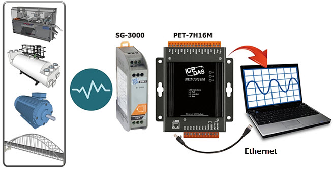
2. Temperature, vibration, strain high speed measurement application
The SG-3000 Series Signal Conditioning Module can be connected to a variety of sensors for current, voltage, thermocouple, resistance temperature sensor (RTD), strain gauge (Strain Gauge), accelerometer Different input signals such as (IEPE Accelerometer) are filtered, isolated, amplified, and converted into an analog voltage or current output in the general measurement range. PET-7H16M/PET-7H24M plus SG-3000 series signal conditioning module will not only monitor voltage, current, temperature, strain, vibration and other diversified signals, but also collect real-time data from different regions and transmit it to the central management system via Ethernet. |
|
| |
|
 |
|
| |
|
| Modules |
SG-3011/H |
SG-3013 |
SG-3016 |
SG-3227 |
| Input |
| Channels |
1 |
1 |
1 |
2 |
| Input signal |
Thermocouple |
RTD |
Strain Gauge |
IEPE Signal Conditioner |
| Type |
J, K, T, E, R, S, B, N, C, L, M, L2 |
Pt100
Ni120
Pt1000 |
±10 mV, ±20 mV,
±30 mV, ±50mV, ±100mV |
IEPE Current: 2 mA, 4 mA, 6 mA, 10 mA ± 5%
AC Signal Gain: 1, 10, 100 ± 2%
High Pass Filter: 10 Hz
Low Pass Filter: x1, x10 : 80 kHz; x100 : 50 kHz |
| Analog Output |
| Channels |
1 |
1 |
1 |
2 |
| Output signal |
0 ~ 10 V,
0 ~ 20 mA |
0 ~ 5 V, 0 ~ 10 V,
0 ~ 20 mA,
4 ~ 20 mA |
±5 V, ±10 V,
0 ~ 5 V, 0 ~ 10 V,
0 ~ 20 mA |
AC Couple: ±10 V,
DC Couple: 1~28 V |
| Applications |
| |
● HVAC/Air conditioning control
● Petrochemical industry
● Electronic/semiconductor equipment
● Water treatment equipment
● Pot/heating industry
● Hot pressing mold |
● VOC Combustion control
● Corrosive temperature measurement
● Air/oil pressure machine
● Solar production equipment
● Desalination equipment |
● Vehicle material research
● Equipment construction
● Boat, bridge structure
● Building structure monitoring |
● Building structure
● Equipment safety detection
● Mechanical vibration measurement
● Structural vibration analysis measurement
● Vibration reduction test
● Machine rigidity test |
|
|
| Refer to http://www.icpdas.com/root/product/solutions/signal_conditioning_modules/sg-3000/sg-3000_selection.html for more details regarding of SG-3000 series. |
|
| |
|
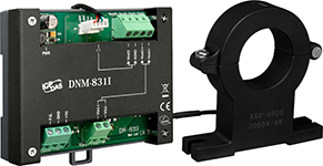
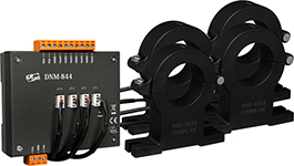
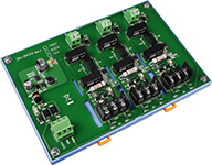
3. High voltage and high current high speed measurement application
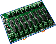
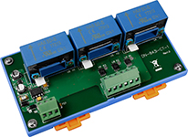
DN-800 series is a Voltage Attenuator and Current Transformer designed for used in high-voltage and high-current applications. The high-voltage and high-current can be converted into ±10 Vpp attenuated signal, and PET-7H16M/PET-7H24M is able to read the ±10 VDC signals via DN-800 series.
By using DN-800 series and PET-7H16M/PET-7H24M, the power data of all kinds of machines and AC/DC motors can be high-speed measured and retrieved, and then the analyzed data can be quickly used to develop a model to build a failure warning system.
|
|
| |
|
| Model |
Input Channel |
Input Type |
Input Range |
CT Type |
Cable |
Output |
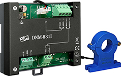 |
DNM-831I-100V-50A |
1 × Voltage,
1 × Current |
AC/DC |
±100 Vpp, ±50 A |
Clip-on Ø21 mm |
1.5 m/2.5 m |
±10 Vpp |
| DNM-831I-100V-200A |
±100 Vpp, ±200 A |
| DNM-831I-100V-500A |
±100 Vpp, ±500 A |
 |
DNM-831I-100V-1000A |
±100 Vpp, ±1000 A |
Clip-on Ø40.5 mm |
1.5 m |
±10 Vpp |
| DNM-831I-100V-2000A |
±100 Vpp, ±2000 A |
 |
DNM-844-50A |
4 × Current |
AC/DC |
±50 A |
Clip-on Ø21 mm |
1.5 m/2.5 m |
±10 Vpp |
| DNM-844-200A |
±200 A |
| DNM-844-500A |
±500 A |
 |
DNM-844-1000A |
±1000 A |
Clip-on Ø40.5 mm |
1.5 m |
±10 Vpp |
| DNM-844-2000A |
±2000 A |
 |
DN-843VI-600V |
3 × Voltage |
AC/DC |
±600 Vpp |
N/A |
N/A |
±10 Vpp |
 |
DN-848VI-10V |
8 × Voltage |
AC/DC |
±10 Vpp |
N/A |
N/A |
±10 Vpp |
| DN-848VI-80V |
±80 Vpp |
| DN-848VI-150V |
±150 Vpp |
 |
DN-843I-CT-1 |
3 × Current |
AC/DC |
±1 A |
Solid Core (closed) |
N/A |
±1.6 Vpp |
| DN-843I-CT-10 |
±10 A |
±10 Vpp |
| DN-843I-CT-20 |
±20 A |
±10 Vpp |
| DN-843I-CT-50 |
±50 A |
±4 Vpp |
|
|
| Refer to http://www.icpdas.com/root/product/solutions/signal_conditioning_modules/dn-800/dn-800_selection.html for more details regarding of DN-800 series. |
|
|
|
 |
|
1. Data transmission mode |
|
| |
1. |
Continuous transmission |
| |
|
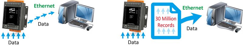
After starting A/D acquisition, data is continuously transmitted to the Host PC. |
| |
|
| PET-7H16M |
| Total simultaneous sampling channels |
Maximum sampling rate per channel |
| 8 |
30 KHz |
| 4~8 |
60 KHz |
| 2~4 |
120 KHz |
| 1 |
200 KHz |
|
| |
|
|
| |
|
| PET-7H24M |
| Total simultaneous sampling channels for PET-7H24M |
Maximum sampling rate per channel |
| 2~4 |
60 KHz |
| 1 |
128 KHz |
|
| |
|
|
| |
2. |
After collecting N data samples, the data is transferred to the Host PC |
| |
|
a. After starting A/D acquisition, the data will be temporarily stored in the memory on the PET-7H16M/PET-7H24M module, and wait until a command is received from the Host PC, before transferring the collected data to the Host PC. |
| |
|
b. The memory capacity allows temporary storage of up to 30 million data samples, Storage time: |
| |
|
(b1) 125 seconds at a sampling rate of 30 kHz
(b2) 19.6 seconds at a sampling rate of 200 kHz |
| |
|
| PET-7H16M |
| Total simultaneous sampling channels |
Maximum sampling rate per channel |
| 1~8 |
200 KHz |
|
| |
|
|
| |
|
| PET-7H24M |
| Total simultaneous sampling channels |
Maximum sampling rate per channel |
| 1~4 |
128 KHz |
|
|
|
| |
|
 |
|
| |
|
2. A/D trigger mode
|
|
| |
1. |
Software A/D Data Acquisition mode |
| |
|
The A/D acquisition parameters are configured via a command from the Host PC. The continuous A/D acquisition or the acquisition of N data samples begins after the command is triggered. |
| |
2. |
External Digital Signal Event Trigger mode (*Only for PET-7H16M) |
| |
|
The A/D acquisition parameters are configured via a command from the Host PC, and then triggered via an external electrical signal. The A/D acquisition of the N data samples is then started. |
| |
3. |
Analog Input Trigger mode |
| |
|
The A/D acquisition parameters are configured via a command from the Host PC, When the analog input value is higher or lower than the set specific voltage value, the A/D acquisition of the N data is started. |
| |
4. |
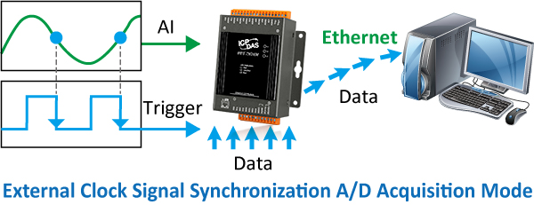
External Clock A/D Conversion Data Acquisition mode (*Only for PET-7H16M) |
| |
|
The speed of the A/D acquisition and the amount of data acquired are controlled by external electrical signals. A falling edge for each output waveform triggers an AD conversion. |
|
|
| |
|
 |
|
| |
|
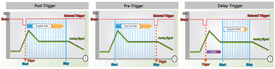
3. External Digital Signal Event Trigger mode (*Only for PET-7H16M)
|
|
| |
A/D acquisition is performed in external digital event trigger mode (triggering the electrical signal is the falling edge trigger). The maximum sampling rate per channel is 200 kHz, and A/D acquisition of N data samples is performed. The acquisition mode can be categorized into two types. |
| |
1. |
Pre-Trigger (acquisition of N data samples) |
| |
|
The A/D data is continually collected and is temporarily stored in the memory on the PET-7H16M until the trigger signal is received. Once the trigger signal is received, the collected N data samples are then transferred to the Host PC. |
| |
2. |
Post-Trigger (acquisition of N data samples) |
| |
|
In this mode, the A/D acquisition of the N data samples is started once the trigger signal is received. |
| |
3. |
Delay-Trigger (acquisition of N data samples) |
| |
|
The A/D acquisition of the N data samples is started once the programmed delay period from the trigger has elapsed. |
|
|
| |
|
 |
|
| |
|
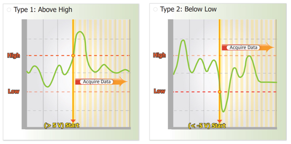
4. Analog Input Trigger
|
|
| |
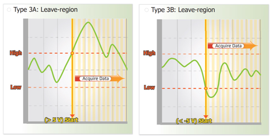
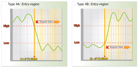
Analog Input Trigger is triggered when the voltage signal of the specified analog input channel is higher or lower than a certain voltage setting. In addition, the user can also specify the trigger voltage level range of the input signal. Once the signal leaves the high and low level region or the signal enters the high and low level region, it is triggered to start the acquisition.
1. Above High: The signal is triggered above the high level and collects N data.
2. Below Low : The signal is triggered below the low level and collects N data |
|
|
 |
|
| |
|
| |
3. Leave-region : Trigger when the signal leaves the high and low level region, collect N data |
|
|
 |
|
| |
|
| |
4. Entry-region : Trigger when the signal enters the high and low level region, collect N data |
|
|
 |
|
| |
|
5. A/D sync trigger between multiple modules (*Only for PET-7H16M)
|
|
| |
The A/D acquisition parameters are configured via a command from the Host PC, and are triggered by an external digital signal event, the A/D acquisition of N data samples, or A/D acquisition via the synchronization of an external clock signal. |
|
|
| |
|
 |
|
| |
|
6. Synchronous Counter input (*Only for PET-7H16M)
|
|
| |
The PET-7h16M is equipped with 4-channel low-speed counters and 1-channel high-speed counter. It can be set to read the counter input synchronously with the A/D sampling time. The counter inputs can be read asynchronously by the software at any time and the counter inputs are also read synchronously with the analog input at the set sampling time. The high speed counter input is the same channel as the hardware trig + / trig- input. If the trig + / trig- input is set to the counter input. External digital signal event triggering and external clock A/D conversion data acquisition cannot be used. |
|
|
| |
|
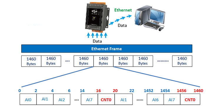
7. Synchronous input data acquisition with flexible data frame
|
|
| |
The features of the previous 1~4 are all about A/D high-speed acquisition, data transmission and trigger mode. In addition to the high-speed acquisition of the analog input, other digital input/digital output read-back and counter input can also be read simultaneously, and these acquisition data can also be transferred to the Host PC with the Analog input sampling data. It is flexibly to define different input types into the Ethernet data frame of synchronous input data acquisition. In synchronous input data acquisition, the sampling rate can be 2KHZ Max.
The Transmit packet of the synchronous input data acquisition is embedded in the Ethernet frame with user-defined data frames. Here are some examples below. |
|
|
| |
1. The following user-defined frame
consists of 8-channel AI value and 1-channel high-speed counter value. |
|
|
 |
|
| |
|
| |
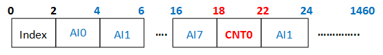
2. The following user-defined frame consists of the index header, 8-channel AI value and 1-channel high-speed counter value. |
|
|
|
|
| |
|
| |
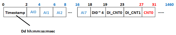
3. The following user-defined frame consists of a timestamp header, an 8-channel AI value, a 4-channel low-speed counter value, and a 1-channel high-speed counter value. |
|
|
|
|
| |
|
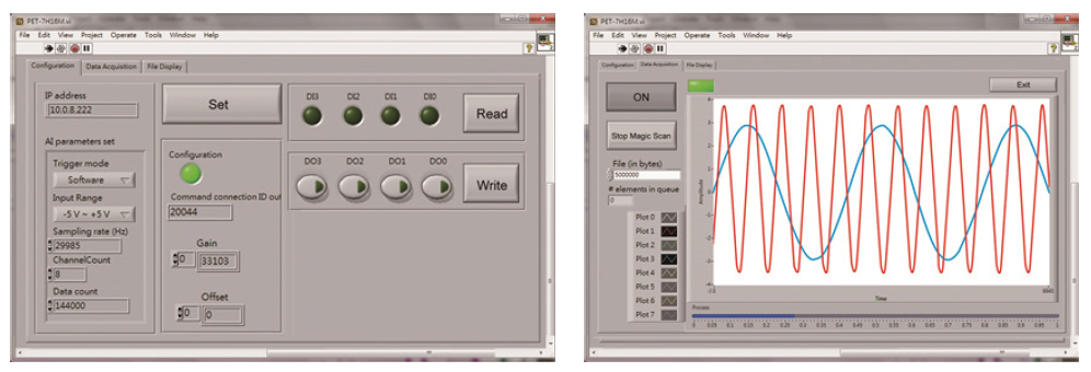
8. Software Support
|
|
| |
- Supported Operating Systems
• Windows 7/8/10 and Linux
- 2. Software Compatibility
• Microsoft VC, C#, VB.NET SDK API and Demo
• NI LabVIEW Toolkit and Demo
• C/C++ library and Demo for Linux
|
|
|
| |
|
 |
|
| |
|
9. Data logger file
The measurement data can be saved as a data logger file by SDK API or the utility with different file types raw data (.bin), text file (.txt), comma separated values file (.csv) or National Instruments TDM and TDMS files.
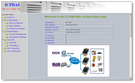
10. Built-in Web Server
Each PET-7H16M/PET-7H24M module has a built-in web server that allows users to easily configure, monitor and control the module from a remote location using a regular web browser. |
|
| |
|
 |
|
| |
|
11. Communication Security
Account and password are required when logging into the PET-7H16M/PET-7H24M web server. An IP address filter is also included, which can be used to allow or deny connections with specific IP addresses. |
|
| |
|
12. Modbus/TCP Protocol
The Modbus/TCP slave function on the Ethernet port can be used to provide data to remote HMI/SCADA software built with Modbus/TCP driver. |
|
| |
|
13. Automatic MDI/MDI-X Crossover for Plug-and-play
RJ-45 port supports automatic MDI/MDI-x that can automatically detect the type of connection to the Ethernet device without requiring special straight or crossover cables. |
|
| |
|
14. Highly Reliable Under Harsh Environment
PET-7H16M/PET-7H24M is housed in a metal shell/case with a column-like ventilator that helps to cool the working environment inside the shell/case.
Operating Temperature: -25 ~ +75 °C
Storage Temperature: -30 ~ +80 °C
Humidity: 10 ~ 90% RH (non-condensing) |
|
| |
|
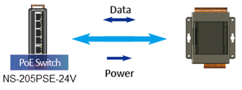
15. PoE (Power over Ethernet)
"P" of PET-7H16M means PoE function. The module has integrated Power-over-Ethernet (PoE), it allows power and data to be carried over a single Ethernet cable, so a device can operate solely from the power it receives through the data cable. This innovation allows greater flexibility in office design, higher efficiency in systems design, and faster turnaround time in set-up and implementation. The module feature true IEEE 802.3af-compliant (classification, Class 1) Power over Ethernet (PoE) using both Ethernet pairs (Category 5 Ethernet cable). The module can receive power from an auxiliary power sources like AC adapters and battery in addition to the PoE enabled network. This is a desirable feature when the total system power requirements exceed the PSE’s (power sourcing equipment) load capacity. Furthermore, with the auxiliary power option, the module can be used in a standard Ethernet (non-PoE) system. |
|
| |
|
 |
|
| |
|
When using PoE devices like PET-7H16M/PET-7H24M, you can choose ICP DAS “PoE” switch —“NS-205PSE” as the power source, NS-205PSE automatically detects the connected devices whether they are PoE devices or not. This mechanism ensures NS-205PSE to work with both PoE and non-PoE devices coordinately at the same time. Being as a power source for PoE devices, NS-205PSE requires its power input ranging from +46 ~ +55 VDC. |
|
| |
|
| TOP |
|
| |
|
| |
|
| |
|
|