|
|
 |
|
| |
|
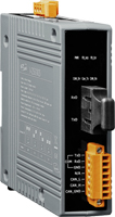
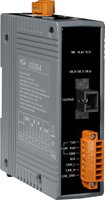
I-2533CS series 
CAN to Single Mode Fiber Bridge |
|
| |
|
|
|
|
| |
I-2533CS
I-2533CS-60
~ Available soon ~ |
I-2533CS-A
I-2533CS-B
~ Available soon ~ |
|
|
|
|
|
| |
|
|
| |
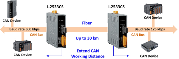
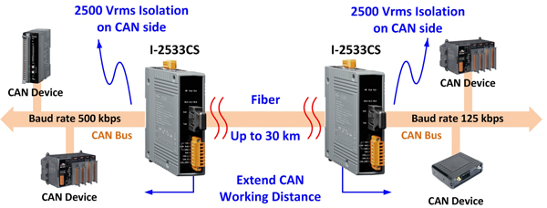
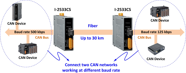
The I-2533CS series (I-2533CS, I-2533CS-60, I-2533CS-A and I-2533CS-B) is a local CAN bridge used to establish a connection between two CAN bus system via single mode fiber optic transmission medium. In order to solve the problem between CAN and fiber transmission medium, the I-2533CS series is specially designed for converting the electrical CAN bus signal to fiber optic cables. Besides, the I-2533CS-A/B supports Wavelength Division Multiplexing (WDM) technology so that only a single fiber cable is needed for transmitting bi-directional CAN data. As the I-2533CS-A and I-2533CS-B must be paired because of hardware limitations, this means that the cost of deploying fiber cable can be effectively reduced.
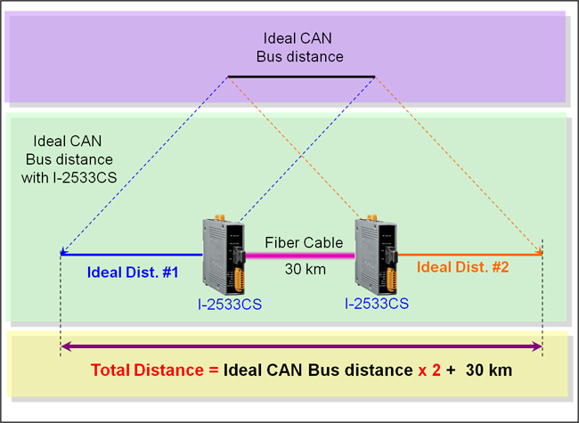
I-2533CS series has three more important features. First, the transmission distance limitation of the CAN bus system will not affected due to the different CAN baud rate. It means that the total CAN bus working distance can be extended. Second, the bus error on one CAN network will not affect the operation of another CAN network. Finally, the two CAN network can communication with each other by using different CAN baud rate for highly flexibility.
|
|
| |
The mainly difference between I-2533 and I-2533CS series are fiber connectors and transmission distance. The I-2533CS series is designed for single mode fiber, and allow to extern CAN bus to maximum 30 km. Besides, I-2533CS provides the group function, which is the basic message router. Users can decide the CAN message flows between several CAN bus systems. I-2533CS series also provides the utility tool for user-defined baud rate and filter configuration. By using this tool, it is allowed to have user-defined baud rate and CAN message filter. When users use the I-2533CS series on two CAN network with different CAN baud rate, it may be useful to reduce the bus loading of the network which has low baud rate. 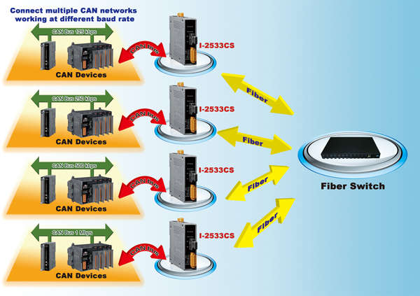
|
|
|
|
|
| |
|
|
| |
|
|
| |
• Control System
•
Building Automation
• Factory Automation
• Distributed
data acquisition
 |
|
| |
|
|
|
|
|
| |
|
|
| |
|
|
| |
- Fiber Type: SC ; Single mode ; 100 Base-FX
- Maximum transmission distance up to 30 km (60km for I-2533CS-60, 15km for I-2533CS-A and I-2533CS-B) at any CAN baud rate
- NXP TJA1042 CAN transceiver
- 2500 Vrms isolation on the CAN side
- Supports both CAN 2.0A and CAN 2.0B
- Fully compatible with the ISO 11898-2 standard
- Rotary switch for CAN baud rate configuration
- Build-in switch for 120 Ω terminator resistor
- Removable terminal block, Mount easily on DIN-Rail
- Allows user-defined CAN baud rate
- Fiber broken line detection
- Utility tool for CAN message filter configuration
- The CAN port with the same Group ID can communicate with each other
|
|
| |
|
|
|
|
|
| |
|
|
| |
|
|
| |
| Model Name |
I-2533CS |
I-2533CS-60 |
I-2533CS-A / I-2533CS-B |
| CAN Interface |
| Connector |
Screwed terminal block (CAN_GND, CAN_L, CAN_H) |
| Baud Rate (bps) |
10 k ~ 1 M |
| Transmission Distance (m) |
Depend on baud rate |
| Terminator Resistor |
Switch for 120Ω terminator resistor |
| Isolation |
3000 VDC for DC-to-DC, 2500 Vrms for photo-couple |
| Specification |
ISO 11898-2, CAN 2.0A and CAN 2.0B |
| Fiber Interface |
| Type |
SC Duplex type ; Single mode ; 100 Base-FX |
SC type ; Single mode ; 100 Base-FX |
| Wave Length (nm) |
1310 |
TX: 1310, RX: 1550 for I-2533CS-A
TX: 1550, RX: 1310 for I-2533CS-B |
| Fiber Cable (μm) |
8.3/125, 8.7/125, 9/125 or 10/125 |
| Transmission Distance (km) |
30 (indicative only) |
60 (indicative only) |
15 (indicative only), (9/125 μm recommended) |
| Min. TX Output (dBm) |
-15 |
-5 |
-8 |
| Max. TX Output (dBm) |
-8 |
0 |
-14 |
| Max. RX Sensitivity (dBm) |
-34 |
-35 |
-31 |
| Max. RX Overload (dBm) |
-5 |
0 |
| Budget (dBm) |
19 |
30 |
23 |
| UART Interface |
| COM1 |
RS-232 (configuration only) |
| COM1 Connector |
Screwed terminal block (RXD, TXD, GND) |
| LED |
| Round LED |
PWR, FB_Ack, FB_Err, CAN_Err, CAN_Tx and CAN_Rx LEDs |
| Power |
| Power supply |
Unregulated +10 ~ +30 VDC |
| Protection |
Power reverse polarity protection, Over-voltage brown-out protection |
| Power Consumption |
0.125 @ 24VDC |
| Mechanism |
| Installation |
DIN-Rail |
| Dimensions |
33.0 mm x 126 mm x 101 mm (W x L x H) |
| Environment |
| Operating Temp. |
-25 ~ 75 ℃ |
| Storage Temp. |
-30 ~ 80 ℃ |
| Humidity |
10 ~ 90% RH, non-condensing |
Note:
The I-2533CS-A and I-2533CS-B is a couple. Users must use pair in the applications. Due to this characteristic, the Group ID of the I-2533CS-A and I-2533CS-B is not used.. |
|
| |
|
|
|
|
|
| |
|
|
| |
|
|
| |
| CAN Baud rate [bit/sec] |
Ideal Fiber Length [km] |
| 1M |
30 |
| 800K |
30 |
| 500K |
30 |
| 250K |
30 |
| 125K |
30 |
| 50K |
30 |
| 20K |
30 |
| 10K |
30 |
|
|
| |
|
|
|
|
|
| |
|
|
| |
|
|
| |
|
CAN to Single Mode Fiber Bridge; 1 single mode, SC connector (RoHS)
|
|
CAN to Single Mode Fiber Bridge; 1 (60 km) single mode, SC connector (RoHS)
|
|
CAN to Single Mode Fiber Bridge ; 1 (15 Km) single mode, SC connector, TX 1310 nm, RX 1550 nm (RoHS)
|
|
CAN to Single Mode Fiber Bridge ; 1 (15 Km) single mode, SC connector, TX 1550 nm, RX 1310 nm (RoHS)
|
|
|
| |
Important Note: You must purchase both I-2533CS-A and I-2533CS-B since these products work as a pair. |
|
| |
|
|
| |
|
|
|
 |
|
| |
|
|
| |
|
7/14 channel Surge Protector
|
|
EMI Ferrite Split/Snap-On Core
|
|
Field-Installation A-coded 5-pin Female
|
|
|
| |
|
|
| |
|
|
|
|