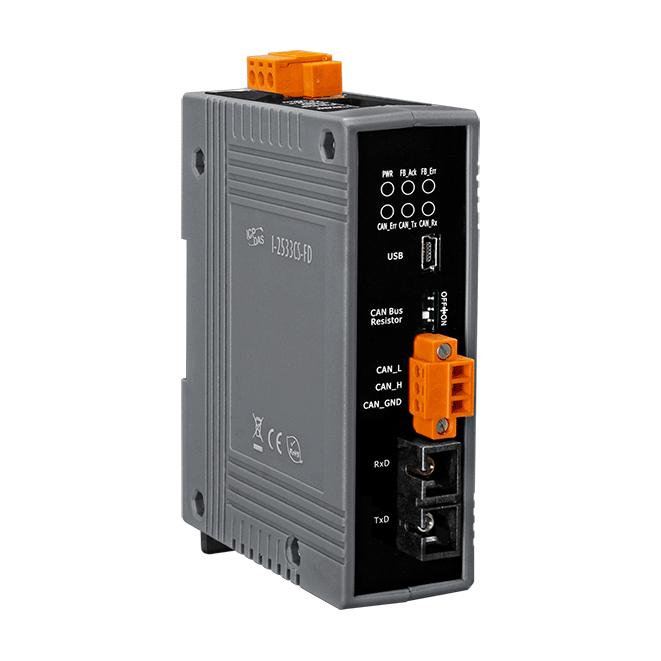
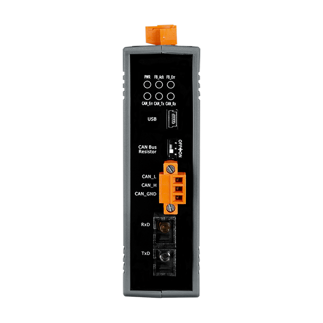
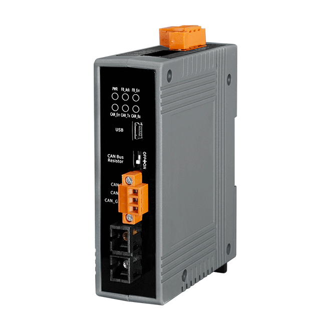
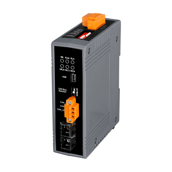
I-2533CS-FD
CAN/CAN FD to Single-mode Fiber Bridge
Features
- Compatible with the ISO 11898-2 standard
- Compatible with CAN specification 2.0 A/B and FD
- CAN FD support for ISO and Non-ISO (Bosch) standards switchable
- CAN FD bit rates for data field from 100 kbps to 10000 kbps
- CAN bit rates from 10 kbps to 1000 kbps
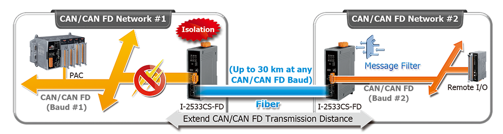
- Fiber broken line detection
- Support CAN Bus message filter configuration
- Support firmware update via USB
- Basic CAN message routing function via Group ID settings.
- Built-in switchable 120 ohm terminal resistor for CAN Bus
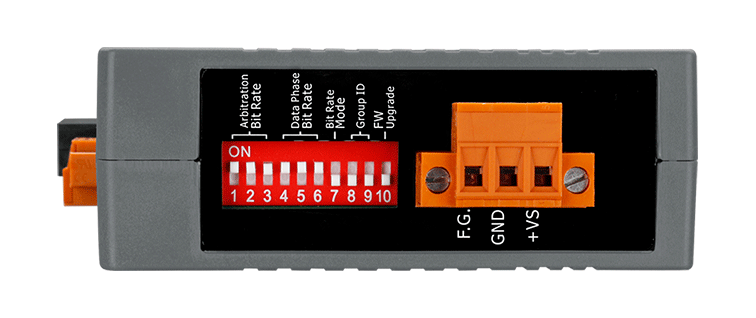
- Dip switch for CAN/CAN FD baud rate configuration
Introduction
The I-2533CS-FD is a local CAN/CAN FD (CAN with Flexible Data-Rate) bridge used to establish a connection between two CAN bus system via single mode fiber optic transmission medium. In order to solve the problem between CAN/CAN FD and fiber transmission medium, the I-2533CS-FD is specially designed for converting the electrical CAN/CAN FD bus signal to fiber optic cables. Besides, I-2533CS-FD has three more important features. First, the transmission distance limitation of the CAN bus system will not affected due to the different CAN/CAN FD baud rate. It means that the total CAN/CAN FD bus working distance can be extended. Second, the bus error on one CAN/CAN FD network will not affect the operation of another CAN/CAN FD network. Finally, the two CAN/CAN FD network can communication with each other by using different CAN/CAN FD baud rate for highly flexibility.
Applications
- Control System
- Building Automation
- Factory Automation
- Distributed data acquisition
Ordering Information
| PRODUCT SERIES | DESCRIPTION | QNT. | INQUIRY |
|---|---|---|---|
Similar Products
| LED Indicators | |
|---|---|
| Status | 1 x Power, 3 x CAN status, 2 x Fiber status |
| Fiber | |
|---|---|
| Fiber Cable | 8.3/125, 8.7/125, 9/125 or 10/125 μm |
| Wavelength | 1310 nm |
| TX Output | -15 dBm Min. , -8 dBm Max. |
| RX Sensitivity | -34 dBm Max. |
| RX Overload | -5 dBm Max. |
| Budget | 19 dBm |
| Propagation Delay | 190 us (*Note1) |
| Distance Between Stations | 30 km (9/125 μm recommended) |
| USB | |
|---|---|
| Specification | USB 2.0 High Speed (480Mbps) |
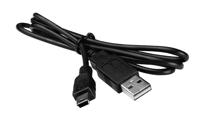
| Connector | USB Type B, Mini-B |
| Driver | Built-in Windows 7/8.1/10 |
| CAN | |
|---|---|
| Ports | 1 |
| Baud Rate | CAN bit rates: 10 k ~ 1 M bps, CAN FD bit rates for data field: 100 k ~ 10M bps (*Note2) |
| Terminal Resistor | Switch for 120Ω terminal resistor |
| Specification | ISO 11898-2, CAN 2.0 A/B and FD |
| Filter | Yes |
| Power | |
|---|---|
| Input Range | +10 VDC ~ +30 VDC |
| Consumption | 3 W |
| Mechanical | |
|---|---|
| Casing | Plastic |
| Dimensions (mm) | 33 x 127 x 101 (W x L x H) |
| Installation | DIN-Rail |
| Environment | |
|---|---|
| Operating Temperature | -25 ~ +75 °C |
| Storage Temperature | -30 ~ +80 °C |
| Humidity | 10 ~ 90% RH, Non-condensing |
Specification Memo
Note2: The maximum CAN FD data rate can be exceeded depending on the concrete operating conditions (cable length, network topology, settings,...), but it can also not be reached.